 Portuguese
  English
  German
  Russian
  Japanese
  Korean
  Spanish
  French
  Italian
 Quick answer:
CNC machining tolerances define how precisely a part can be manufactured compared to its intended dimensions. Standard CNC machining typically achieves ±0.005 inches (±0.127 mm), while tight-tolerance work can reach ±0.001 inches (±0.025 mm) or tighter depending on the material and geometry. For most industrial applications, general tolerances are sufficient. Only critical mating surfaces, seal interfaces, or high-precision assemblies require tighter specifications. Over-specifying tolerances is one of the most common and costly mistakes in CNC procurement, often increasing part cost by 30 to 100 percent without adding real functional value.
This guide covers the tolerance ranges you should know, how material selection affects achievable precision, which applications demand tighter controls, and the practical factors that determine your final cost and lead time. Whether you are designing a production part or evaluating a prototype, understanding these fundamentals helps you make confident specification decisions.
Understanding CNC Machining Tolerâncias
Tolerance in CNC machining refers to the allowable deviation from a specified dimension. Every machined part will vary slightly from the digital model due to material behavior, tool wear, thermal expansion, and machine limitations. The tighter the tolerance, the more control is required throughout the entire manufacturing process.
General-purpose CNC machining from a professional CNC machining service provider typically holds ±0.005 in (±0.127 mm) across most materials and features. This range covers the vast majority of industrial components, including brackets, housings, mounts, and structural parts. Functions that do not involve precision fits, sealing, or alignment usually perform well within this band.
Tight-tolerance CNC machining operates in the range of ±0.001 to ±0.0005 in (±0.025 to ±0.0127 mm). These specs are essential for aerospace bearings, medical implant components, hydraulic manifolds, and optical instrument housings. Achieving them requires specialized fixturing, controlled environmental conditions, and often multi-step finishing operations.
Some manufacturers can push below ±0.0005 inches, but those capabilities come with significant cost premiums and longer cycle times. They are reserved for applications where functional failure is not an option. Understanding where your part falls on this spectrum is the first step toward smart specification.
How Material Affects Achievable Tolerances
The material you select directly influences the precision floor of your machined part. Different metals and plastics respond differently to cutting forces, heat generation, and residual stress relief. Ignoring material behavior during the specification phase frequently leads to scrapped parts or post-process distortion.
Aluminum alloys such as 6061 and 7075 are among the easiest materials to machine to tight tolerances. Their consistent grain structure and moderate hardness allow stable cutting with minimal deflection. Parts from these alloys can routinely hold ±0.001 inches without special handling procedures.
Stainless steel and titanium are significantly more challenging. These materials work-harden during cutting, generate high thermal loads, and exert greater tool pressure. Tight tolerances on stainless steel or titanium usually require slower feed rates, multiple roughing and finishing passes, and careful stress-relief planning. Expect a noticeable jump in cost compared to equivalent aluminum parts.
Engineering thermoplastics like PEEK, Delrin, and PTFE introduce their own variables. Polymers expand and contract with temperature changes and can deform under clamping force. Machining them to sub-thousandth tolerances is possible but demands temperature-controlled environments and low-pressure fixturing strategies.
Material selection should never be divorced from tolerance requirements. Material selection for CNC machining should always consider both functional performance and manufacturability constraints together.
General vs. Tight Tolerance: When to Choose Which
Choosing between general and tight tolerances is one of the most consequential decisions in the CNC procurement process. Specifying unnecessarily tight tolerances drives up cost with no measurable improvement in part performance. Conversely, underspecifying tolerance on a critical feature can cause assembly failure or premature wear in the field.
General tolerances are appropriate for non-critical features such as cosmetic surfaces, mounting holes that do not align with precision pins, external profiles, and structural cutouts. Parts in these categories often pass quality inspection on the first attempt and require no secondary operations.
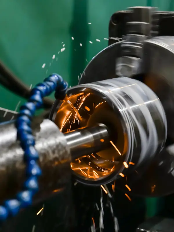
Tight tolerances become necessary when parts interface with other precision components, form fluid seals, carry rotational loads, or maintain critical clearances. Bearing seats, shaft bores, flange faces,and threaded interfaces are typical candidates for tighter control.
If you are unsure which level your part requires, precision CNC milling engineers at YPMFG can review your design and recommend appropriate tolerance zones before quoting. This consultation often prevents over-specification and reduces total project cost.
Key Factors That Influence Tolerance Achievement
Several variables work together to determine whether a given tolerance is achievable on a specific part. Ignoring these factors during the design phase creates friction during production and increases the likelihood of rejected components.
Part geometry plays a major role. Long, slender features deflect under cutting force and are difficult to hold to tight tolerances regardless of machine capability. Thin walls, deep cavities, and overhanging sections each introduce unique stability challenges that require tailored fixturing and toolpath strategies.
Machine condition and calibration matter significantly. A well-maintained five-axis center from a reputable CNC turning and milling services provider will consistently outperform an older, poorly calibrated machine even if both share the same nominal specifications. Tool presetter calibration, spindle runout, and linear encoder accuracy all contribute to repeatable tolerance achievement.
Coolant temperature and shop floor conditions affect dimensional stability, particularly for aluminum and plastic parts. Thermal growth during extended machining cycles can shift measurements by several thousandths of an inch. Professional shops monitor these variables and compensate through programmed offsets and scheduled measurement checks.
Workholding strategy determines how much the part moves during cutting. Improper clamping can distort a part enough to push it outside tolerance before the tool even touches the material. Soft jaws, vacuum fixtures, and custom nests are common solutions to this problem.
Common Mistakes in Tolerance Specification
Over-specifying every dimension to ±0.001 inches is the single most frequent and expensive error in CNC part design. This habit assumes tighter is always better, which is simply not true in practice. Every additional decimal place of precision adds cost, extends lead time, and sometimes creates new manufacturing problems.
Another common mistake is listing tolerances without indicating datums or reference surfaces. A tolerance value without a clear datum chain is ambiguous and leaves the machinist to interpret your intent. This often results in parts that meet the numerical spec but fail to assemble correctly in the field.
Ignoring geometric dimensioning and tolerancing standards is the third frequent error. GD&T symbols such as true position, flatness, perpendicularity, and concentricity communicate functional intent far more precisely than basic tolerance callouts alone. Parts specified only with bilateral tolerances leave critical relationships undefined.
Failing to specify which features require tight tolerances and which can remain general leads to confusion on the shop floor. A clear tolerance map that identifies critical features upfront saves time for both the designer and the manufacturer.
Tolerance Comparison by Feature Type
The table below summarizes typical tolerance ranges across common feature types in CNC machining. These values represent what a competent CNC machining parts manufacturer can consistently achieve under normal production conditions.
These ranges serve as a practical starting point for specification. Your actual achievable tolerance depends on part size, material, machine availability, and the specific sequence of operations required.
How Tolerances Affect Cost and Lead Time
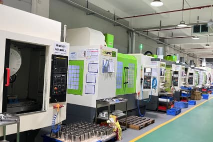
Tolerance directly drives manufacturing cost and production timeline. Moving from a general tolerance of ±0.005 inches to a tight tolerance of ±0.001 inches often doubles or triples the machining time for a given feature. Each additional quality check, each slower cutting pass, and each secondary finishing operation adds to the bottom line.
Surface finish requirements are closely linked to tolerance cost. Achieving a fine surface finish on a tight-tolerance feature often requires a separate grinding or lapping step. This secondary operation adds both time and expense to the quote.
Inspection and documentation costs rise with tighter tolerances. Parts held to ±0.0005 inches typically require first-article inspection reports, CMM verification, and statistical process control tracking. These administrative and equipment costs are real and must be factored into your procurement budget.
For YPMFG customers, CNC machining quotes include detailed tolerance notes and cost breakdowns so you can see exactly where each specification impacts price. This transparency lets you adjust your design before committing to production.
Design Tips for Better Tolerance Outcomes
Designing parts that are easy to machine to your target tolerances saves money and reduces risk. The earlier you incorporate manufacturing awareness into your design, the fewer surprises you will encounter during production.
Keep feature sizes proportional to machine travel and tool length. Extremely small features on a large part may require micro-tools that break easily and machine slowly. Consider whether a smaller part or a split design could achieve the same function with better yield.
Provide adequate material stock around tight-tolerance features. A pocket or bore surrounded by insufficient wall thickness may flex during cutting and spring back after the tool passes. Adding extra material and then machining to final dimension produces a more stable result.
Specify tolerances only on features that require them. Annotating every dimension with a tight callout does not improve part quality. It slows down the machinist, complicates inspection, and inflates your cost.
Communicate functional intent clearly. Including a brief note explaining why a particular tolerance matters helps the engineer choose the right machining sequence and inspection method. YPMFG engineers review these notes during the engineering evaluation stage and suggest optimizations when possible.
Quality Verification and Inspection Practices
Verifying that a part meets its specified tolerances is a structured process that involves multiple measurement techniques. No single method is sufficient for full compliance validation.
Visual inspection checks surface finish, burrs, and obvious defects. Optical comparators verify profile shapes and angular features against master templates. Coordinate measuring machines provide the most comprehensive dimensional verification by probing key points across the part surface.
Caliper and micrometer measurements cover basic linear dimensions and are useful for quick shop-floor checks. For positional features, pin gauges and go-no-go gauges provide fast acceptance testing without the setup time required for CMM programming.
Professional suppliers provide inspection reports with actual measured values, not just pass or fail labels. This data gives you confidence that the part meets your requirements and provides a record for your quality management system.
Common Questions Buyers Ask About CNC Machining Tolerances
What tolerance should I specify for a non-critical bracket?
A general tolerance of ±0.005 inches is typically sufficient. Reserve tighter calls for mounting holes, bolt patterns, and any surface that mates with another component.
Can the same part be machined in both aluminum and stainless steel to the same tolerance?
Both materials can reach ±0.001 inches, but stainless steel and titanium require slower cutting, more passes, and greater care. Expect higher cost and longer lead time for equivalent tolerances in harder materials.
Why does my quote include a tolerance surcharge?
Tolerance surcharges reflect additional machining time, specialized tooling, extra inspection steps, and tighter process controls required to hold tighter specs. They are a normal part of precision machining pricing.
How do I know if my CAD model has proper tolerance annotations?
Check that every critical feature has an explicit tolerance value, that datums are defined, and that GD&T symbols are applied where needed. If the model only shows nominal dimensions, the manufacturer must interpret your intent, which introduces risk.
What is the difference between tolerance and surface finish?
Tolerance controls dimensional accuracy. Surface finish controls the texture and roughness of a machined face. Both affect part performance but are specified independently. A part can have excellent dimensional tolerances and poor surface finish, or vice versa.
Do I need a first-article inspection for my order?
First-article inspection is recommended for tight-tolerance parts, new suppliers, or regulated industries. It verifies that your complete design intent is met before full production begins and creates a documented baseline for future orders.
Choosing the Right CNC Machining Partner for Your Tolerance Needs
Achieving your target tolerances consistently depends on the capabilities and processes of your manufacturing partner. A shop that invests in calibrated equipment, trained programmers, and structured quality systems will deliver more reliable results than one that relies on ad hoc practices.
Evaluate potential suppliers on their documented tolerance capabilities, inspection equipment, and experience with your target material. Request sample reports from previous similar projects when possible. YPMFG offers free engineering assessments to help you validate your tolerance strategy before committing to production.
Ask about their process controls for tight-tolerance work. Inquire whether they use statistical process control, environmental monitoring, and tool-life management. These practices separate professional precision shops from general-purpose machine shops.
Making a Better Long-Term Decision on Tolerances
The right tolerance specification balances functional requirement against manufacturing reality. Overspecifying wastes budget. Underspecifying risks field failure. Both outcomes are unnecessary when you have clear technical guidance and an experienced manufacturing partner.
YPMFG supports designers and procurement teams at every stage of this process. From custom CNC machining solutions and detailed engineering reviews to precision quote comparisons, our team helps you specify intelligently and produce reliably. Send your drawings or specifications to YPMFG for a free engineering evaluation and competitive quote.