 Russian
  English
  German
  Japanese
  Korean
  Spanish
  French
  Italian
  Portuguese
 Краткий ответ:
PTFE machining is the process of shaping polytetrafluoroethylene into functional parts using turning, milling, drilling, or routing operations. Because PTFE softens at relatively low temperatures, expands significantly under heat, and has far less stiffness than metals, parameters borrowed from aluminum or steel setups will melt the workpiece at the cutting edge. Successful PTFE machining therefore demands reduced cutting speeds, sharp positive-geometry tooling, active chip control, and gentle clamping forces.
If you have tried to machine a PTFE bar on a standard CNC lathe, you probably watched the material drag, soften, and produce inconsistent chips. Обработка на станках с ЧПУ of PTFE is not just a matter of swapping the workpiece and running the same G-code. The material’s low elastic modulus, high thermal expansion, and self-lubricating surface change how every operation behaves. YPMFG works with engineers and procurement teams who need PTFE parts held to tight tolerances without distortion or surface scoring.
What this guide covers:
Why PTFE resists conventional machining parameters
The specific speeds, feeds, and tooling that work
A comparison of turning, milling, drilling, and routing
Practical questions buyers ask before placing an order
Why PTFE Resists Conventional Machining
PTFE has a continuous service temperature limit around 260 °C, but the material begins to soften noticeably above 150 °C. When a cutting tool generates friction heat at the interface, the workpiece locally loses rigidity and flows instead of forming a clean chip.
This creates three core problems in sequence. The chip welds back onto the tool edge, ruining surface finish and dimensional accuracy. The part expands during the cut and contracts after cooling, shifting final dimensions. Excessive clamping force deforms the workpiece before the cut even begins.
Most failed PTFE jobs trace back to one root cause: parameters copied from a metal-machining setup without any material-specific adjustment. The fix is to rethink speed, feed, tool geometry, and fixture design from the polymer’s perspective, not the metal default.
PTFE Machining Parameters and Tooling
The single most important adjustment is cutting speed. For Токарная обработка с ЧПУ of PTFE, typical surface speeds range from 300 to 600 m/min, well above what you would run on most metals. Feed rates stay conservative, usually 0.1 to 0.5 mm per revolution, to limit chip thickness and heat input at the edge.
Tool geometry matters as much as speed. Use a large positive rake angle, a sharp nose radius, and a polished flank to reduce chip adhesion. Carbide inserts with a smooth, low-friction coating outperform uncoated high-speed steel in continuous production runs.
Chip management is the third factor. Long, stringy PTFE chips can wrap around the tool or the workpiece itself. A chip-breaker groove in the insert or a directed air blast at the cutting zone keeps the area clear. In most cases, flood coolant is unnecessary and can trap heat at the interface; dry cutting or a light mist is the preferred approach.
PTFE Machining Methods at a Glance
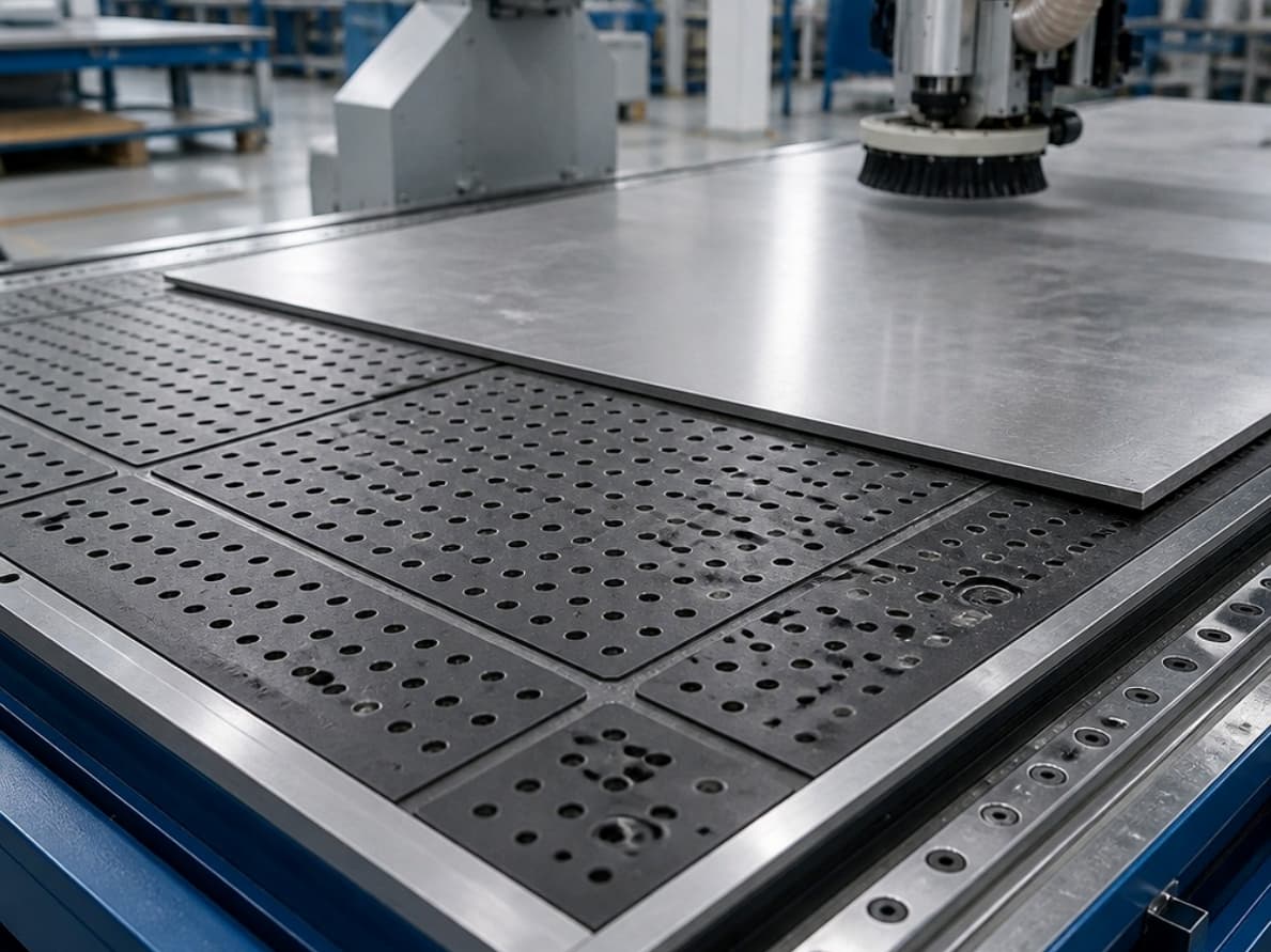
If your part is rotationally symmetric,turning of PTFE gives the best surface finish and the shortest cycle time. Complex, non-symmetric features call for Фрезерование с ЧПУ with a rigid, low-force fixture. For large flat panels and gaskets, a router running at high spindle speed with minimal vertical force avoids deflection.
Common Questions About PTFE Machining
Can I machine PTFE on the same CNC machine I use for aluminum?
Yes, but the parameter set must change entirely. Reduce feed, increase speed, swap to a sharp positive-geometry insert, and remove flood coolant. Keep the fixture gentle; PTFE deforms under clamping pressure, so use soft jaws or V-blocks instead of hard vise plates.
What tolerance can I realistically hold on a machined PTFE part?
With proper fixturing and thermal management, ±0.02 mm is achievable on turned features. Milled surfaces typically land in the ±0.05 to 0.1 mm range. Always allow for post-machining thermal recovery; the part shifts slightly once it cools to ambient temperature.
Does PTFE need a primer or adhesive before machining?
No. PTFE is machined in its solid, virgin, or filled form. Bonding is a post-machining step. If your application requires adhesive or coating, surface treatment such as PTFE surface preparation (fluorination, plasma etching, or a compatible primer) is applied after the geometry is complete.
Which PTFE fillers improve machining performance?
Glass-filled, bronze-filled, and carbon-fiber-reinforced blends are the most common options. Filled grades increase stiffness and reduce creep, which helps hold tolerances during and after machining. Confirm the specific filler type and its thermal behavior with your material supplier before locking in parameters.
## Need Help Selecting PTFE Machining for Your Project?
The core decision comes down to three inputs: your dimensional tolerance, the geometry type, and the filler grade you are using. Get those three right and the PTFE machining path becomes straightforward.
YPMFG reviews your part drawings, suggests the optimal method and parameter window, and flags potential thermal-recovery or deformation risks before production starts. Send your specifications, material grade, and tolerance callouts for a tailored engineering review and project-specific quote.