 Spanish
  English
  German
  Russian
  Japanese
  Korean
  French
  Italian
  Portuguese
 Respuesta rápida: 5 axis CNC machined parts are components whose geometry requires five-axis tool orientation to reach multiple faces in a single setup. You need them when undercuts, angled holes, or complex contoured surfaces cannot be accessed on a 3 axis machine without flipping the part. The trade-off is a higher per-part rate, offset by shorter total build time, better cross-feature accuracy, and reduced cumulative alignment error.
If you are evaluating whether a complex component justifies a 5 axis setup, the decision touches part cost, lead time, and achievable Tolerancias de las piezas mecanizadas con CNC all at once. YPMFG works with engineering teams to determine whether 5 axis CNC machining is genuinely required or whether a simpler fixture route meets your specification. The sections below cover the practical factors that drive that call.
What to read in this guide:
What makes 5 axis parts different from 3 axis
When 5 axis is the right call
Cost drivers and a pre-order checklist
Questions buyers ask before placing an order
How to make the setup decision for your next part
What Makes 5 Axis Parts Different from 3 Axis

The core difference is tool access. A 3 axis machine moves along X, Y, and Z. A 5 axis machine adds two rotational axes, letting the tool approach the part from virtually any angle. Undercuts, spherical surfaces, and angled features can be cut in one clamping instead of four or five.
Para 5 axis CNC machined parts, that single-setup capability reduces cumulative positioning error. Each flip on a 3 axis machine introduces new alignment uncertainty, which compounds when Tolerancias de las piezas mecanizadas con CNC are in the ±0.01 mm range. The table below shows where the difference becomes practical.
The table highlights where 5 axis changes the outcome versus where a well-planned 3 axis route is sufficient.
When 5 Axis Is the Right Call
Before committing to a 5 axis process, check three things. Does your part have features on four or more distinct faces that interact geometrically? Are the surfaces organic rather than simple prismatic shapes? Would multiple setups push your tolerance budget beyond what the application allows?
In aerospace and medical applications, the answer is often yes. Impellers, surgical instruments, and turbine housings demand tight cross-feature alignment that is difficult to hold across four separate setups. Selección de materiales also matters: cutting titanium or Inconel on a 5 axis machine keeps the tool at the optimal approach angle, reducing heat buildup and tool wear.
If your part is a bracket, plate, or simple housing with features on two to three faces, a 3 axis setup will typically cost 30 to 50 percent less and deliver the same functional result. The 5 axis premium is justified by geometry, not by marketing.
Cost Drivers and a Pre-Order Checklist
Five-axis parts carry a higher per-unit cost than equivalent 3 axis parts. The gap comes from machine-hour rate, tool changes, CAM programming complexity,and fixture design. A well-prepared specification narrows the quote range considerably.
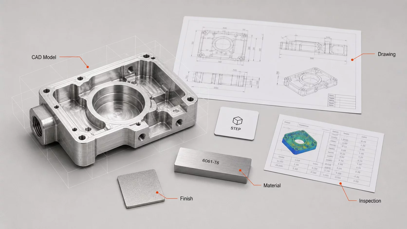
Before sending a drawing for a quote, run through this checklist:
Map every face, hole, and contour that must be reached
State the critical tolerance and its reference datum
Confirm selección de materiales: alloy grade, heat treatment, surface finish
Note volume and timeline: one-off prototype versus a run of 500
Decide on inspection method: CMM, laser scan, or go/no-go gauges
Flag any assembly context where the part mates with neighboring components
YPMFG’s engineering team can review your drawing against this checklist and identify features that may not need 5 axis access. That review often trims unnecessary complexity before you commit to a full quote.
Preguntas que se hacen los compradores antes de realizar un pedido
Does 5 axis always produce a better part?
Not automatically. If your geometry is prismatic and tolerances are moderate, 3 axis delivers the same result at lower cost. 5 axis earns its premium when multi-face interaction and single-setup accuracy drive the design.
Can one 5 axis machine handle aluminum, steel, and titanium?
Most 5 axis machining centers can, but feed rates, cutting speeds, and coolant strategy change with each material. Titanium in particular runs slower and generates more heat. Ask how your supplier manages tool wear across mixed-material batches.
How much more will 5 axis add to my part cost?
Expect roughly 20 to 60 percent above a comparable 3 axis part, depending on setup time, tool changes, and CAM path length. The exact delta shifts with part size and material.
What files should I send for a 5 axis quote?
Send a STEP or IGES 3D model plus your 2D drawing with tolerances. A PDF with notes helps but is not enough for CAM programming. If you have a custom CNC part solution in mind, include the assembly context so the engineer can evaluate fixture access and tool reach.
Making the Right Setup Decision for Your Next Part
Choosing between 3 axis and 5 axis is a geometry-and-tolerance call, not a “more axes is better” assumption. When you are unsure, send your drawing, material spec, and tolerance callouts to YPMFG for an revisión técnica. The team identifies which features genuinely need 5 axis access, which can be simplified, and where fixture changes could lower your per-part cost without sacrificing accuracy. You get a clear recommendation before spending on a full quote.