English
 German
 Russian
 Japanese
 Korean
 Spanish
 French
 Italian
 Portuguese

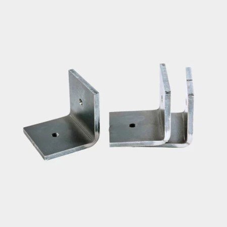
Sheet Metal Fabrication comes with small habits that CAD never shows you: metal stretches when it folds, it springs back afterward, and heat pushes it around. Here’s a list of six things to look at before a drawing goes out. Five minutes of checking can save you far more time than remaking a part.
1. Pick the Metal and Thickness First
Choose the metal first, because it determines how the part folds. Aluminum 5052 bends well and resists corrosion, making it a common choice for covers and enclosures. Stainless steel 304 has an attractive bare finish, but it’s springier and harder on tools, which can affect the manufacturing quote.
Cold-rolled steel is affordable and strong, but it can rust quickly after cutting, so painting or powder coating should be included in the budget. Galvanized steel provides a protective zinc coating, but welding requires care because zinc fumes can be hazardous and the coating can burn away around the seam.
Choose a Suitable Aluminum Grade
Aluminum 6061-T6 catches people out. It’s excellent for many machined parts but can be difficult to bend because its hardened temper increases the risk of cracking along the fold. If you need 6061 aluminum for a bent component, ask your supplier about a more suitable temper and the required forming process.
Keep the Sheet Thickness Consistent
Keep to one thickness if possible. Introducing a second gauge may require additional tooling adjustments, setups, and handling, increasing production costs.
2. Choose How the Sheet Gets Cut
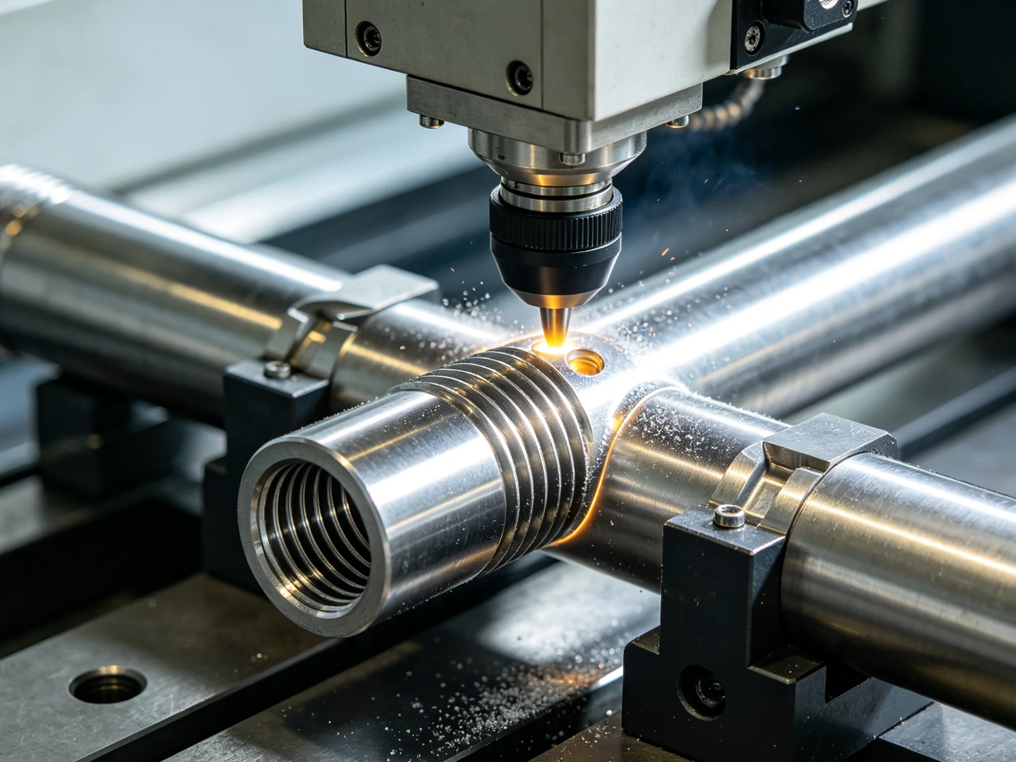
For cutting, most shops go straight to the laser, and that’s often a good choice. Laser Cutting is fast and can achieve tolerances around ±0.1 mm under suitable conditions. Thin and medium-thickness sheets are generally efficient to process.
The laser also creates a narrow cut, known as the kerf, which may be around 0.1 to 0.3 mm depending on the material, thickness, and cutting settings. Manufacturers account for this during programming.
Consider the Cut Edge and Surface Finish
People sometimes forget the edge. Oxygen-cut steel can develop an oxide layer that may affect subsequent finishing. Powder coating requirements should be discussed with the fabricator so the surface can be prepared correctly. Nitrogen-assisted laser cutting can produce a cleaner, brighter edge in suitable applications, although it may cost more.
If the edge will be visible or painted, specify your expectations before production begins.
When to Use Waterjet and Tube Laser Cutting
Waterjet Cutting is another option. It uses high-pressure water, often mixed with an abrasive, to cut material without introducing the same heat-affected zone associated with thermal cutting. It can process thick plate and materials such as stone, glass, and composites.
The trade-offs include slower cutting speeds in many applications, a wider kerf that may approach 1 mm, and possible taper through thicker material. Waterjet cutting is worth considering when heat-related distortion or material damage is a concern.
For tube or pipe components, Tube Laser Cutting can create notches, holes, and angled ends in a single programmed setup, reducing the need for separate cutting operations.
3. Respect the Bend
Metal Bending is where designs can get into trouble. A press brake forms the sheet using a punch and die, so the inside bend radius depends on the tooling, material, and forming method.
Choose the Correct Bend Radius
A sensible starting point for many sheet metal designs is an inside bend radius close to the material thickness. However, the appropriate radius depends on the alloy, temper, thickness, and grain direction. A radius that’s too tight can cause cracking, especially in harder or less ductile materials.
Keep bend radii consistent throughout the design where practical. This can reduce tooling changes and help control production costs.
Keep Holes Away from Bend Lines
Holes near a bend can distort as the material stretches during forming. As an initial design guideline, consider keeping the nearest edge of a hole at least 2.5 times the sheet thickness plus the inside bend radius away from the bend line. The exact clearance depends on the hole size, tooling, material, and forming process, so confirm it with your supplier.
Flanges also need enough length to remain stable during forming. A short flange may not sit securely in the tooling, making it difficult to achieve the intended bend. The required minimum length depends on the press brake setup and die opening.
Add Bend Reliefs and Specify Tolerances
When two bends meet near an edge, add a suitable bend relief to reduce tearing and material distortion at the corner. Relief dimensions should account for the sheet thickness, bend radius, and part geometry.
Bend angles also have different tolerance requirements from flat laser-cut features. Depending on the material and process, angular tolerances around ±0.5° to ±1° may be achievable. Flange dimensions can also vary slightly after forming.
If a particular angle or dimension is critical to assembly, clearly identify it on the drawing and discuss the tolerance with the fabricator.
4. Think About Joining Early
Many sheet metal components consist of multiple pieces. If an enclosure needs welded corners, discuss the available Welding Services with your supplier before finalizing the model.
Spot welds and short welds can limit heat input in suitable applications. Long, continuous weld seams may distort thin sheet metal, requiring additional straightening or grinding and increasing labor costs.
Choose the Right Joining Method
When welding isn’t necessary for strength or sealing, alternatives such as tabs and slots, rivets, and press-in hardware can simplify assembly.
Many well-designed Custom Enclosure products combine joining methods. Welds provide rigidity at selected corners, while removable fasteners allow access to internal components during maintenance.
5. Plan the Finish While the Model Is Open
Decide on Surface Finishing before finalizing the drawing. Powder coating adds thickness to the surfaces, which can affect tight-fitting tabs, slots, holes, and mating components. The coating thickness depends on the specified finish and application process.
Identify any surfaces that must remain uncoated for electrical grounding, conductivity, or assembly. The manufacturer can mask those areas during finishing.
Select a Finish That Matches the Material
- Powder coating: Provides a durable decorative and protective finish for many steel and aluminum parts.
- Anodizing: Commonly used for aluminum to improve corrosion resistance and provide decorative finishes.
- Brushed finishing: Creates a directional grain that can help establish a consistent appearance on visible surfaces.
- Bead blasting: Produces a more uniform, textured surface on compatible materials.
- Painting: Provides color and protection when the correct preparation and coating system are used.
Grain direction matters, too. Bending across the grain rather than along it can reduce cracking risk in some materials and conditions. On brushed stainless steel, grain direction is also highly visible, so specify the desired orientation when appearance matters.
6. Send Flat Files and Test a Sample
Provide your manufacturer with clear files and consistent specifications. A typical sheet metal fabrication package includes the following:
- DXF flat pattern: Defines the profile to be cut, including the intended flat layout.
- STEP 3D model: Shows the intended folded geometry and helps the manufacturer understand the final component.
- PDF engineering drawing: Lists critical dimensions, bend angles, tolerances, hardware, material, and finish requirements.
The flat pattern defines what to cut, while the 3D model shows the intended finished shape. Make sure the files agree on dimensions and manufacturing requirements. If they conflict, the manufacturer may need to request clarification before production.
Order Samples Before Full Production
Then order two or three sample parts. Fold them, install the hardware, and check whether the lid closes and the assembly fits as intended.
Testing a small batch is a relatively inexpensive way to identify problems before they affect a larger production order. Verify critical dimensions and finishing requirements before approving the final run.
Conclusion
Good Sheet Metal Fabrication often comes down to a few practical decisions made early. Choose the right material and thickness, select a suitable cutting process, use appropriate bend radii, and keep holes away from bend lines.
Plan joining methods and surface finishes before the drawing is finalized. Provide consistent manufacturing files, confirm critical tolerances, and test sample parts before approving full production.
These checks can reduce rework, control manufacturing costs, and improve the chances that your sheet metal component arrives flat where it should be flat and folded where it should fold.