English
 German
 Russian
 Japanese
 Korean
 Spanish
 French
 Italian
 Portuguese

A turned part burr is a thin metal projection left where the cutting tool exits the workpiece. On a 6061 shaft, burr height typically stays under 0.1 mm with a clean tool exit, but soft brass can push it past 0.3 mm. The removal method is fixed by part geometry and material, not by operator preference.
Most buyers treat turned part burr removal as a minor finishing step and discover it is not. A missed burr on a seal face causes field leakage. A file mark on a mating bore fails incoming inspection against ISO 2768 class m. The cost lands as rework, rejected batches, and line downtime, not in the deburring labor itself. YPMFG reviews this step during the DFM stage so the method is locked before the first cut.
Key Takeaways
- Burr height threshold: Most drawings cap machined-edge burrs at 0.1 mm; anything above triggers a second pass or a different tool.
- Material drives the route: Soft brass and 6061 form long, pliable burrs; 316L and H13 form short, stiff ones needing a harder tool.
- Geometry locks the choice: Bores under 12 mm cannot take a standard deburring wheel; wire brushing is the only practical path.
Turned Part Burr Removal: Method Comparison
The right method matches part geometry, material hardness, and the surface finish you must protect, not the fastest option in the shop.

Below a 12 mm bore on 316L, skip the wheel and run a wire brush. Above 50 pieces on steel shafts, a 300-grit bonded wheel clears the burr and holds finish in one rotation.
What Actually Causes Burrs on a Turned Part?
A burr forms at the tool exit where the cutting edge tears instead of shearing. Three variables control height: feed rate, clearance angle, and material ductility. Feed above 0.3 mm per revolution on 6061 roughly doubles the burr compared to the same feed on 316L.
Clearance angle matters more than most operators check. A 10-degree clearance on soft brass produces a long, curled burr that a wheel pushes back into the bore. Raising clearance to 15 degrees shortens it and lets it snap off on the next pass.
Variables That Move Burr Height
- Feed rate: Above 0.3 mm/rev on soft alloys, burr height climbs quickly.
- Clearance angle: Below 8 degrees on stainless, the tool rubs and burrs persist.
- Ductility: Brass and 6061 form longer burrs; H13 and 316L form shorter, stiffer ones.
No tool geometry eliminates burr entirely on a ductile material. You can minimize it to under 0.05 mm with a sharp single-point insert, but the final fraction still needs a finishing pass. Budget for that step in the route.
Which Method Fits Your Part Geometry?
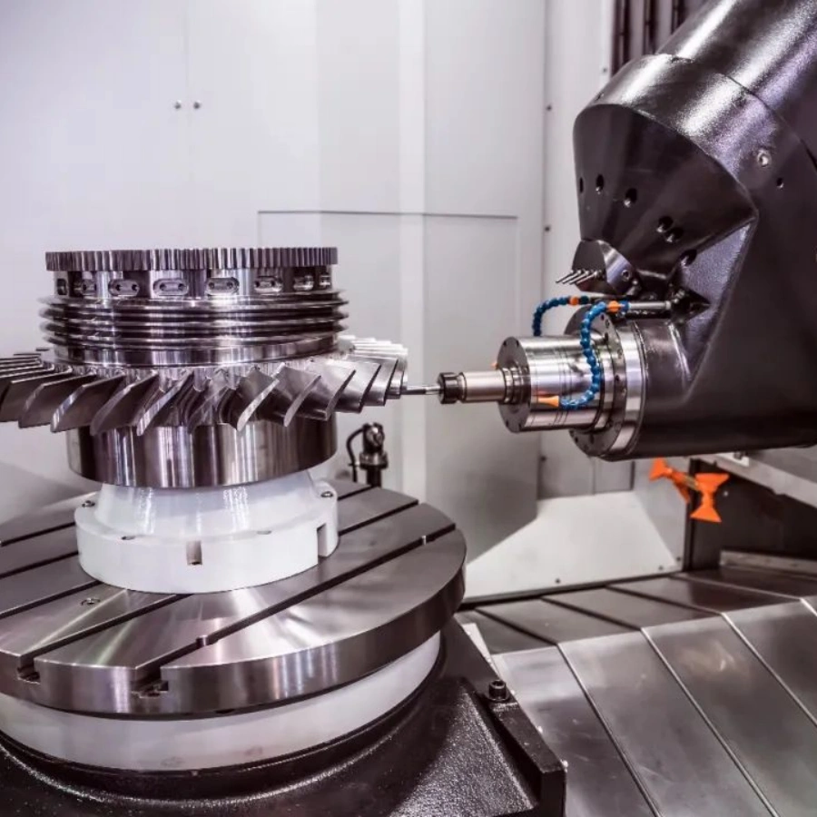
Geometry is the first filter, not material. A through-hole, a stepped shaft, and an external thread each need a different route, even when cut from the same 304 billet.
Through-holes over 12 mm take a standard deburring wheel in a secondary pass. The wheel rides the bore wall and shears the burr in one rotation. Stepped shafts with a shoulder under 8 mm cannot hold a wheel without the face striking the shoulder. A wire brush deburring pass or a flexible shaft is the safe option there.
Threads add a constraint. The burr sits inside the thread runout, and a wheel cannot reach it without gouging the crests. A fine file or thread-specific brush is the only route that preserves the profile. If your spec calls for a clean runout on a 316L fastener, file-and-brush is not optional.
YPMFG locks the deburring method into the DFM review before cutting. If your drawing shows Ra 0.8 but the plan still calls for a 150-grit wheel, the finish will not hold. Send the drawing early and the method gets confirmed on the 3-day sample.
The physical limit to acknowledge: a wheel cannot clean a bore smaller than its own diameter. If the bore is 8 mm and the smallest available wheel is 10 mm, you must redesign the part or switch to a brush route.
How YPMFG Handles a Typical Deburring Job
The walkthrough below covers a batch of 304 stainless flanges, 60 mm OD, 24 mm bore, with a 1.5 mm chamfered edge and a Ra 1.6 flat face.
Process Route Steps
- Cut and rough-turn: 3-axis CNC, feed 0.25 mm/rev on OD, 0.2 mm/rev on bore. Burrs expected at 0.15 mm on both faces.
- Deburring pass: 150-grit bonded wheel on the face, wire brush on the 24 mm bore. Wheel speed matched to material to avoid chatter marks.
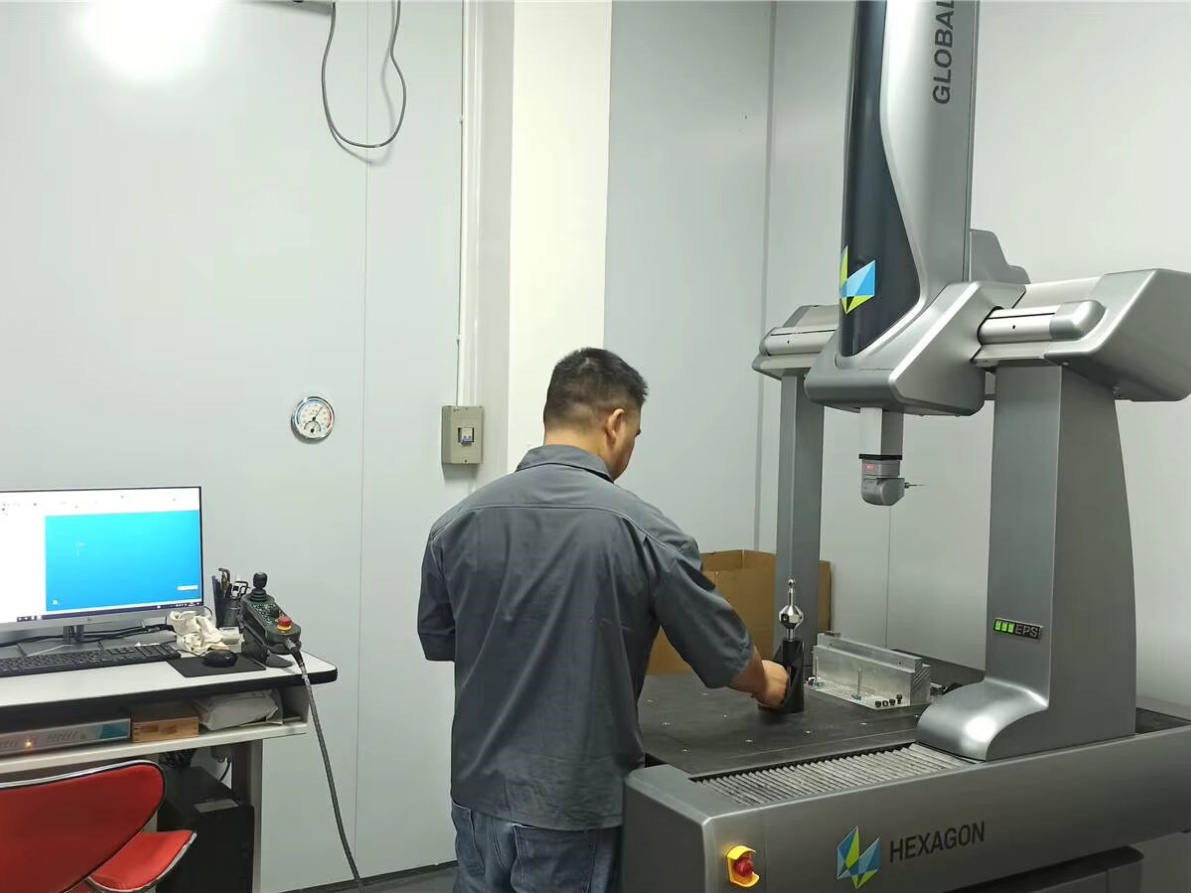
- Finish-check: Visual under 10× magnification for burr height; dye-penetrant check on the chamfer edge for hidden fold-back.
- Final QA: Dimensional check against drawing, Ra measurement on the face, go/no-go gauge on the bore.
Process Route Reference: YPMFG process library, reviewed against published tooling data. Client-specific dimensional data withheld per NDA.
For orders under 20 pieces, the same route runs manually with a file and brush, finishing within the standard 3–7 day window. At 50 pieces and above, the wheel-and-brush secondary pass becomes the default.
Practical Questions Before You Spec Burr Removal
Does burr removal come included in the machining quote? No. It is a separate finishing operation. If a quote says “CNC machining” only and your drawing notes “deburr all edges,” that step is not in the price.
Can a deburring wheel handle 316L without marking the surface? It cannot. A standard 150-grit wheel at high RPM leaves circumferential chatter marks on 316L. A 300-grit wheel at lower speed, or a wire brush, is the correct route for stainless above 30 HRC.
What is the smallest bore you can deburr without redesign? Practically,6 mm with a wire brush. Below that, bristle deflection is too high to reach the far wall cleanly. A vibratory tank or a laser method is the fallback, and those are separate capability checks.
How do I specify this on my drawing without over-constraining the supplier? State the maximum burr height, for example “max 0.1 mm on all machined edges,” and the Ra limit on seal faces. Do not name the tool. The supplier selects the method; you specify the result.
Choosing the Right Burr Removal Path for Your Next Order
The cost of a missed burr is not the deburring labor; it is the failed inspection, the rework cycle, and the downtime at your customer’s line. Locking the removal method into the DFM review before the first cut removes that risk. YPMFG flags geometry that will not clean with a standard wheel during the engineering review and writes the burr-height target into the process plan so the part arrives ready to pass incoming inspection. Send your specifications or drawings for that review. You will get a method recommendation, a rough lead-time estimate with a 3-day sample and 3–7 days for small batches, and a written burr-height target attached to the quote.