English
 German
 Russian
 Japanese
 Korean
 Spanish
 French
 Italian
 Portuguese

Shaft machining tolerance is the single biggest cost lever on a turned part. A ±0.005 mm grinding finish on a 40 mm journal adds roughly 40 percent to unit price versus a standard turned part at ISO 2768-mK. Each added step—turning, heat treatment, grinding—extends lead time and introduces a new failure point.
Most buyers send a shaft drawing and ask for a quote, but the real question is whether every specified tolerance is functionally necessary. Over-tolerancing a non-critical feature adds grinding hours, tightens inspection gates, and pushes the part into a longer queue. YPMFG works with procurement teams to flag which features truly need sub-0.01 mm control and which can hold at default tolerances without affecting assembly.
Key Takeaways for Shaft Buyers
- Concentricity to datum: Radial runout above 0.02 mm on a rotating shaft causes vibration; specify concentricity when the part has two or more stepped journals.
- Material selection: 4140 alloy steel handles torsional stress; 304 stainless resists corrosion but machines roughly 30 percent slower than 1045 carbon steel.
- Heat treatment window: Quenched-and-tempered shafts must rest 24 hours before final grinding to prevent dimensional drift of 0.003 mm.
- Lead time baseline: A standard 3-axis turned shaft ships in 3–7 days; add 5–10 days for heat treatment and grinding.
Which Machining Process Fits Your Shaft Geometry?
The process chain depends on cross-section complexity and the tightest geometric call-out. A simple stepped round shaft with two journals and one keyway is a one-setup lathe job. Add a 90-degree cross-hole, an internal spline, or a contoured profile, and the part moves to 3-axis or 5-axis milling.

If three or more features on your drawing demand grinding, ask whether switching from an interference fit to a press fit removes one grinding step entirely.
What Material and Heat Treatment Should a Shaft Use?
Material selection is about matching the load case, not just the corrosion environment. A 20 mm drive shaft in a gearbox sees torsional shear; a 20 mm guide shaft in a linear actuator sees axial compression and bearing contact stress. The wrong choice means in-service failure, not a test-bench miss.
Carbon and alloy steels (1045, 4140, 4340) handle high torque and can be quenched-and-tempered to 28–34 HRC. Stainless 304 and 316L resist corrosion in food or marine duty but machine 25–40 percent slower. Aluminum 6061 suits lightweight, low-torque applications where weight savings outweigh strength.
Heat Treatment and Dimensional Drift
Quenching a 4140 shaft above its critical temperature and tempering to 30 HRC shifts diameters by 0.002–0.006 mm. The part must rest 24 hours minimum before the final grinding pass; otherwise the work-hardened layer relaxes and the finished dimension drifts out of tolerance. Specifying “grind after rest” on the drawing prevents this mode. No turning operation can replicate a ground finish below Ra 0.8 without adding a separate grinding cell.
How Does Tolerance Stacking Kill a Shaft Assembly?
Tolerance stacking is the most common reason a machined shaft fails at the assembly bench even though each dimension is in spec. Three journals, two bearings, and a spacer accumulate; if each holds ±0.01 mm, the worst-case stack can exceed the housing bore by 0.04 mm. The shaft simply will not seat.
The fix is to specify geometric tolerances—runout, concentricity, straightness—relative to a single datum rather than stacking independent positional tolerances. ASME Y14.5 provides the framework for controlled-feature pairs that keep cumulative error bounded. When reviewing a drawing, check whether the datum scheme is consistent and whether the tightest geometric call-out matches the mating bore tolerance.
What to Verify Before Sending a Drawing
- Datum scheme: One primary datum, usually the centerline of the longest journal.
- Fit class: Bearing fits specified per ISO 286 or the bearing manufacturer catalog.
- Grind allowance: 0.05–0.10 mm stock on all heat-treated surfaces.
- Material cert: EN 10204 3.1 mill test report for the alloy grade.
How a Typical Drive Shaft Moves Through the Shop
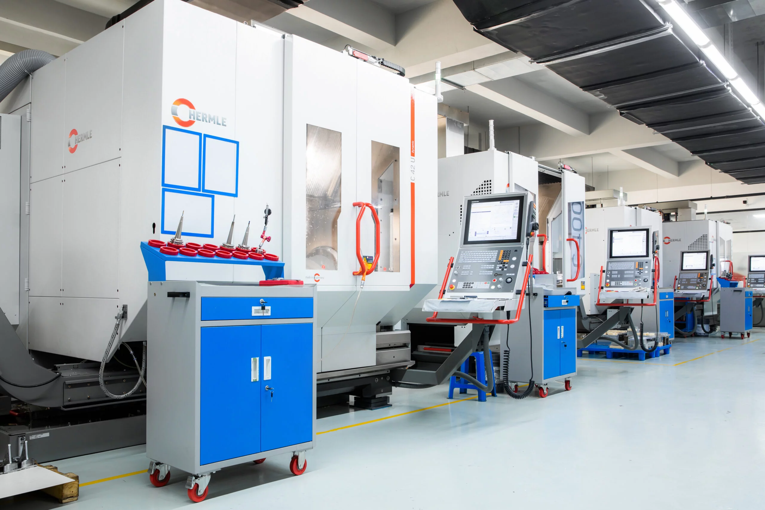
A 60 mm diameter, 200 mm long 4140 drive shaft with two bearing journals, one keyway, and one threaded end follows a defined route. Knowing this route helps you estimate realistic lead time and identify where your schedule is most exposed.
- Rough turning (3-axis lathe): Remove bar stock to 0.05 mm above finish dimension. Cycle 25–40 min. Inspect: mic on all ODs.
- Keyway milling: Cut the DIN 6885 keyway at N9 fit. Cycle 10–15 min. Inspect: pin gauge.
- Heat treatment: Quench and temper to 30–34 HRC. Soak time depends on cross-section. Rest 24 hours minimum.
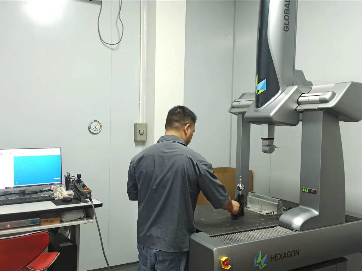
- Finish grinding: Bring both journals to H6, ±0.005 mm. Cycle 15–20 min per journal. Inspect: CMM.
- Final inspection: Runout on both journals, thread go/no-go, surface finish verify at Ra 0.8 max. Report filed with batch record.
Process route reference: YPMFG process library, validated against published tooling and heat-treatment data. Client-specific cycle times and batch records withheld per NDA.
Common Questions Before Ordering a Machined Shaft
Can a CNC lathe hold ±0.003 mm on a shaft?
No. A 3-axis turning center typically holds ±0.01 mm on repeated ODs. ±0.003 mm requires a grinding operation, which adds a separate setup and extends lead time by 3–5 days.
What is the difference between runout and concentricity?
Runout measures total indicator reading of a surface as it rotates; concentricity checks that two cylindrical features share one axis. For a two-journal shaft, concentricity to a single datum is the correct call-out. Runout alone does not control axis alignment.
Do I need a material certificate for a 4140 shaft?
For any shaft entering a safety-critical or regulated application, yes. Request an EN 10204 3.1 mill test report showing chemistry and mechanical properties. YPMFG includes this document at no extra cost on standard steel orders.
How much does a grinding pass add to cost?
Depending on part size and journal count, a cylindrical grinding step typically adds 20–45 percent to the base turning cost. The exact figure scales with the number of ground features and the required finish grade.
Getting the Right Shaft Spec in Hand
The most expensive mistake in shaft machining is not the part itself; it is the rework cycle caused by an ambiguous drawing. A clear datum scheme, a consistent fit-class call-out, and a stated grinding allowance eliminate most back-and-forth with the machine shop. If your current drawing leaves these open, the first step is a tolerance review, not a quote.
You can send your shaft specification to YPMFG for an engineering review. The team will flag which features can relax to default tolerances, confirm the material and heat-treatment route, and return a revised drawing with a firm lead-time window. No minimum order; a single prototype and a 500-piece production run move through the same validation gate. Send the drawing and receive the review within one business day.