English
 German
 Russian
 Japanese
 Korean
 Spanish
 French
 Italian
 Portuguese

For aerospace work, tool selection is driven by 3 hard constraints: material compatibility, tolerance stack-up, and traceability documentation. A carbide end mill that handles 7075-T6 cleanly will not survive Inconel 718 without re-geometric design. Verify your tooling against the actual alloy, not the generic “aerospace-grade” label.
You are likely choosing aerospace manufacturing tools for a part that will face fatigue, thermal cycling,and strict inspection regimes. The wrong tool geometry or fixture can push your first article inspection into rework or scrap. YPMFG works with buyers on tooling selection so the part holds spec on the first run, not the fourth.
Key Takeaways
- Material compatibility: A tool qualified for 6061 aluminum fails fast on Ti-6Al-4V; match coating and geometry to the alloy before quoting cycle time.
- Fixture design: Aerospace brackets with 3 or more fastening holes need a 5-axis CNC setup to hold all datums simultaneously; a 3-axis vise adds 2 to 4 hours per part.
- Traceability documentation: Buyers typically require AS9100-aligned records, material certs, and dimensional reports; plan 15 days for full documentation packaging.
- Tolerance stack-up: A 0.1 mm cumulative tolerance across 4 machined features shifts inspection from CMM to optical; confirm the measurement method before committing to tool path.
How Do You Match a Tool to the Actual Alloy?
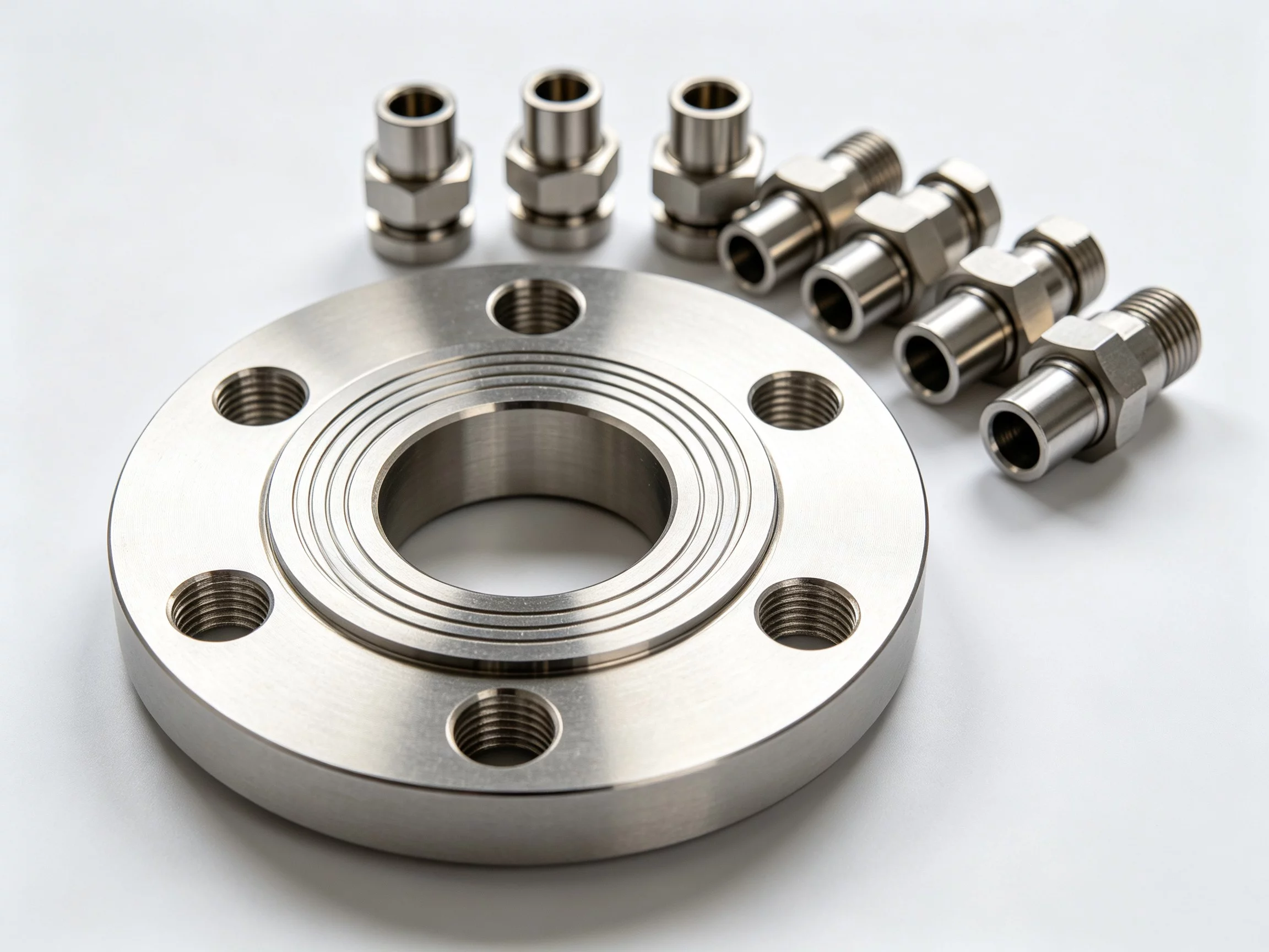
The single biggest error in aerospace tooling is picking geometry from a generic “aerospace” catalog. Titanium, Inconel, and aluminum each demand different rake angles, inserts, and cutting speeds. Start with the alloy datasheet, not the tool brochure.
Coating and Geometry by Alloy
For 7075-T6 aluminum, a standard carbide end mill with a 3-flute geometry runs clean at moderate feeds. For Ti-6Al-4V, shift to a 2-flute or ball-nose geometry with lower cutting speed to manage heat. Inconel 718 often requires a CBN insert; standard carbide burns out within a few passes depending on the cutting parameters.
Check 3 parameters before ordering: coating type (TiAlN for titanium, uncoated for aluminum), minimum recommended cutting speed from the tool vendor, and maximum chip thickness the holder allows. YPMFG can review your alloy spec sheet and flag geometry mismatches before you commit to a tool purchase.
Rule of thumb: if the tool vendor cannot confirm chip thickness for your specific alloy at your feed rate, do not order that tool for production.
Where Do Fixture and Workholding Decisions Go Wrong?
Aerospace parts with multiple fastening surfaces and asymmetric geometry break standard vise setups. A part that needs 4 datums held at once typically requires a custom fixture design on a 5-axis CNC machine. Trying to flip the part on a 3-axis table adds setup time and introduces a new tolerance stack-up at every reposition.
Clamp Point Mapping
Three failure modes dominate: thermal growth of the fixture between clamping and cutting, springback after releasing a thin-wall bracket, and datum shift when a part sits on only 2 contact points. Each one pushes the part outside the tolerance window you planned for.
- Thermal control: Specify the fixture material and allow a 30-minute stabilization window before final cut passes.
- Springback compensation: Add a calculated offset to the CAM program; verify with a test cut on the same alloy thickness.
- Clamp point mapping: Map all clamp locations against fastening holes and critical features to avoid deflection in the measured zone.
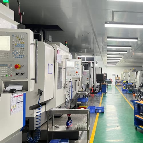
A 5-axis setup eliminates 2 of these 3 failure modes by cutting all features in one clamping operation. The trade-off is fixture cost and a longer CAM programming cycle. The 3-day sample lead time from YPMFG covers most single-operation aerospace brackets.
What Should a Process Route Look Like for a Typical Aerospace Bracket?
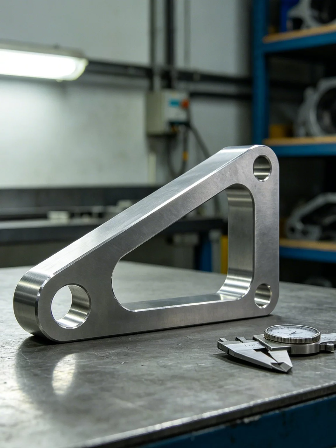
A common aerospace bracket is a 7075-T6 plate, 3 to 8 mm thick, with 4 to 8 fastening holes, 1 or 2 boss features, and a milled datum face. The process below is the standard route YPMFG uses for this part class.
Step 1: Saw cut to blank size with a 0.5 mm allowance on all sides. Step 2: Face mill the datum to flatness within 0.02 mm. Step 3: 5-axis CNC for all through-holes and boss features in a single clamp. Step 4: Deburr and clean. Step 5: CMM or optical inspection per the drawing callout. Step 6: Package with material cert and dimensional report.
If your bracket has 3 or more datums that must hold simultaneously, the 5-axis route is the safer call. For simpler 2-face parts, a 3-axis setup with careful fixture design keeps cost down without sacrificing tool life or dimensional stability.
Process Route Reference: YPMFG process library, reviewed against published tooling data. Client-specific data withheld per NDA.
Practical Questions Before You Commit to a Tool Set
Does a tool rated for “aerospace” automatically meet AS9100 documentation requirements? No. The tool itself is a manufactured item; AS9100 applies to the quality system producing it. You still need the tool vendor to provide material certs, heat treat records, and geometric inspection data that your auditor will accept.
Can one end mill handle both 5052 and 6061 in the same job? It cannot. The 2 alloys have different chip thickness thresholds and recommended feeds. Running a single tool across both adds unpredictable wear and shifts the cutting edge geometry performance window for each material.
How do you verify a fixture will not shift during a 20-hour unattended run? Check clamp torque against calculated deflection at the farthest cutting point, and add a mid-run CMM check at the 8-hour mark. If the datum moves more than 0.02 mm, stop and re-clamp before the next feature.
Making a Safer Long-Term Tooling Decision
The right fixture design and tool geometry save rework, scrap, and audit findings that compound over a program life of 3 to 5 years. The cost of a mis-specified end mill is not just the tool; it is the inspection failure, the NCR, and the schedule slip your customer absorbs.
You can send your drawing set, alloy spec, and target quantity to YPMFG for an engineering review. The team will flag geometry mismatches, fixture risks, and documentation gaps before you spend money on tooling. You also receive a written process route with key control points and the inspection method for each critical dimension, so your quality team knows exactly what to expect on the first article package.
The goal is straightforward: the part passes spec on run one, the documentation clears audit, and the tool is still performing on the last batch of the program.