Spanish
 English
 German
 Russian
 Japanese
 Korean
 French
 Italian
 Portuguese

Yes, but only for specific geometries. Powder-bed metal printing handles internal channels and lattice structures that Mecanizado CNC cannot reach; solid, flat, or tightly toleranced parts still go to 5-axis CNC. The split is a geometry call, not a cost call.
Aerospace procurement teams face a recurring problem: a part with internal fuel passages or a complex bracket needs either powder bed fusion o Mecanizado CNC, and picking the wrong route means rework, failed certification, or a six-week delay. YPMFG works across both processes, so buyers get a geometry-based process call before a purchase order goes out.
Key takeaways at a glance:
- Material certification: Only Ti-6Al-4V, Inconel 718, AlSi10Mg, and 17-4PH hold full aerospace PBF qualification under ASTM standards.
- Tolerance gap: As-printed PBF tolerance sits near ±0.1 mm; Tolerancia CNC holds ±0.02 mm on critical bore features.
- Geometry rule: Internal passages and lattice cores favor printing; flat mated faces and threaded holes favor CNC.
Most aerospace PBF parts go through secondary Mecanizado CNC for critical faces. You print the bulk geometry, then machine the five or six surfaces that must mate or seal.
What Can 3D Printing Actually Handle in Aerospace?
Short answer: internal geometry. Powder-bed fusion builds layer by layer, so a fuel injector with seven passages, a turbine vane cooling channel, or a lattice-core bracket all come out in one build. A 3-axis or 5-axis mill cannot reach those hidden features without splitting the part into sub-assemblies.
The Tolerance Ceiling
The limitation is equally clear. PBF cannot produce a flat, sealed airfoil surface better than 3.2 µm without secondary grinding. It also cannot hold ±0.01 mm on a mating bore. The typical route is: print the complex core, then Máquina CNC the critical faces to final dimension.
Before you choose PBF, check three things: maximum part size in the build envelope, minimum wall thickness for your geometry, and whether the material lot carries a tratamiento térmico certificate traceable to ASTM B381 for Ti-6Al-4V or the equivalent spec for your alloy.
Which Materials Carry Aerospace Certification?
Not every powder is qualified. Four alloys dominate aerospace PBF: Ti-6Al-4V, Inconel 718, AlSi10Mg, and 17-4PH. Each must carry a material heat-treatment certificate and, for flight-critical parts, an ISO 9001 traceable lot record from the powder supplier.
Polymers Are Ground Support Only
Polymer PBF—SLS, MJF, FDM—works for mock-ups,jigs, and non-structural interior components. It is not flight-qualified for load-bearing use at altitude. If your part sees pressure cycles above 30,000 ft, metal PBF or CNC is the only route.
Check two documents before you accept a quote. The powder spec must reference ASTM F2898 or ISO 20628, not a generic “aerospace grade” label. The finished part must pass a FAI to AS9102 Rev D before it ships. If the supplier cannot produce both, your incoming inspection will reject the batch.
Where Does 3D Printing Lose to CNC?
CNC wins on three fronts: surface finish, dimensional repeatability, and threaded features. A milled face hits 1.6 µm; an as-printed face sits at 10-20 µm. A CNC bore repeats within ±0.01 mm across 500 parts; a PBF bore drifts closer to ±0.05 mm lot to lot. A PBF machine cannot cut an M8 internal thread—that needs a tap, which means a CNC operation.
Concentricity and Corner Radius Limits
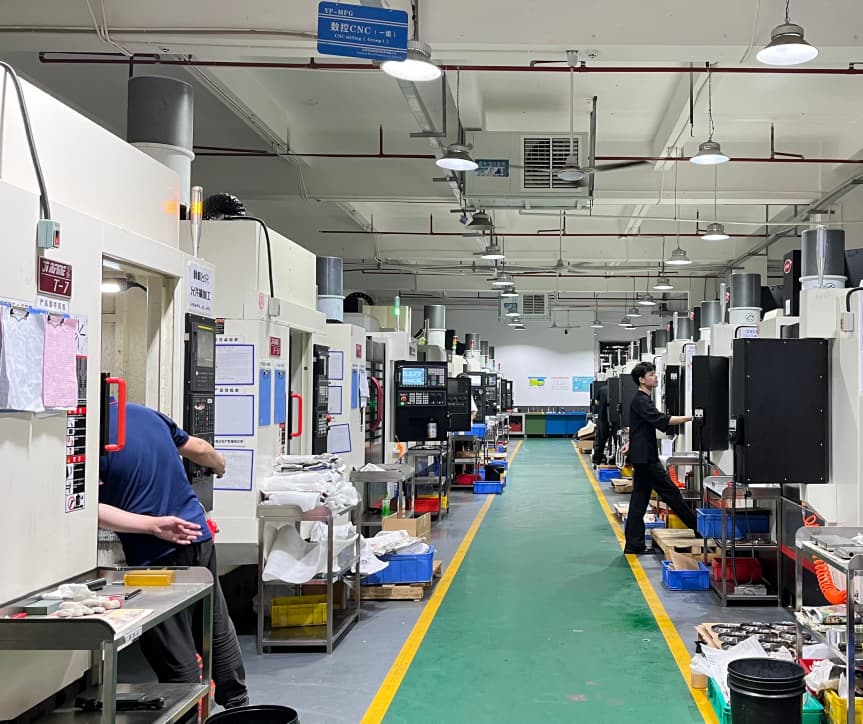
What PBF cannot do: hold concentricity better than 0.02 mm on a bore-shoulder-bore stack, or produce a sharp 90-degree internal corner. That corner needs EDM or a secondary mill pass, adding cost and a setup. The rule of thumb: if your drawing shows more than six critical datums or any feature tighter than ±0.05 mm, route those features to CNC de 5 ejes and print the rest. YPMFG runs a hybrid cell where a PBF batch feeds directly into 3-axis and 5-axis CNC, so the part moves without leaving the shop.
How a PBF-to-CNC Route Handles a Turbine Bracket
A typical aerospace bracket: Ti-6Al-4V, internal cooling passages, three mounting bosses, one sealed bore. Here is the process route YPMFG runs on that class of part.
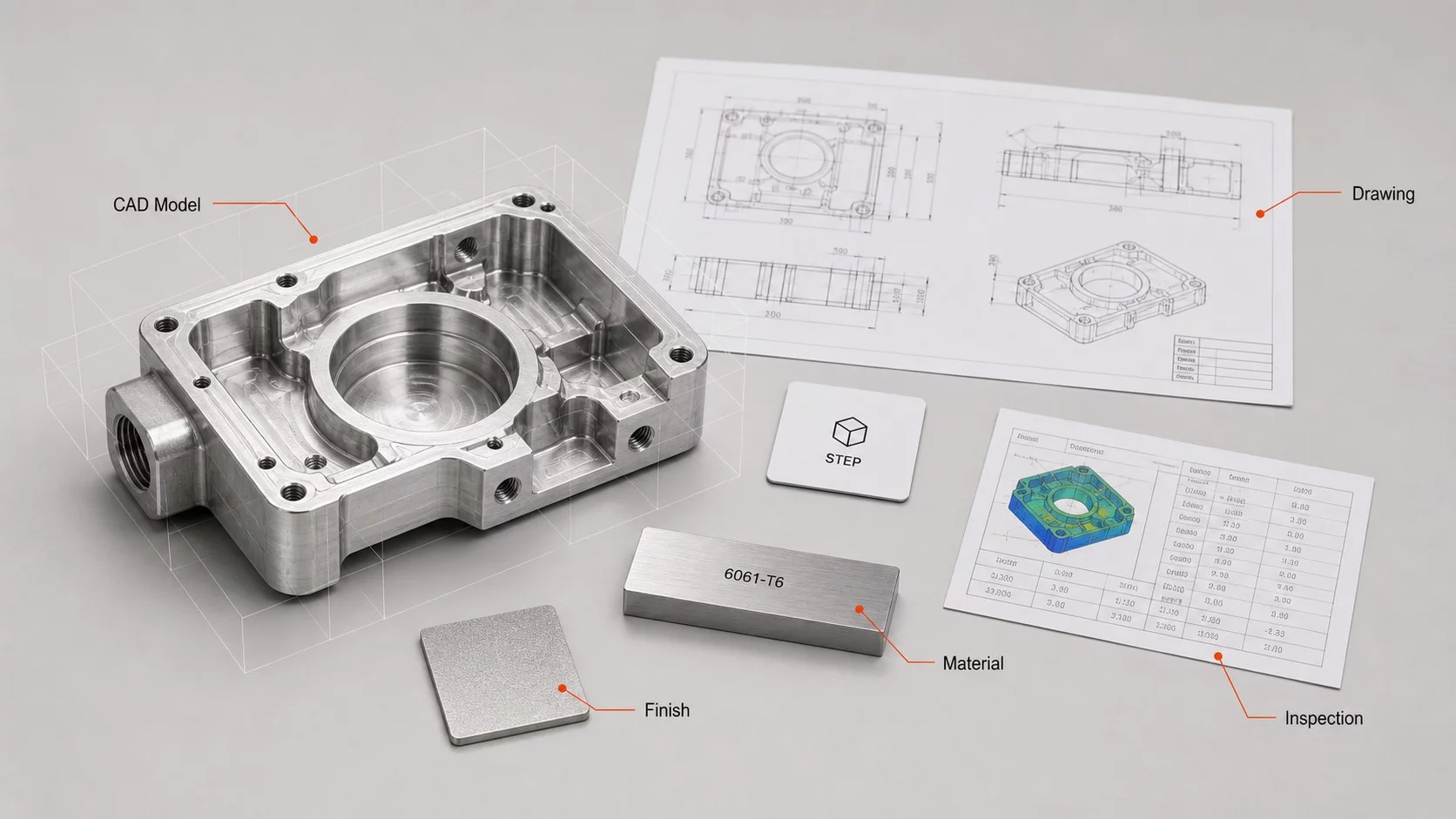
- DFM review: orient the bracket so cooling passages print without support; confirm 0.8 mm minimum wall. Flag the sealed bore for post-machining.
- PBF build: three units in one batch, 80 µm layer height, 4-hour stress-relief anneal at 650 °C.
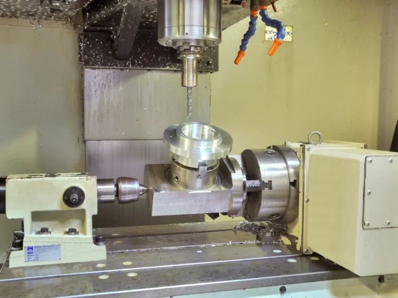
- Secondary Mecanizado CNC: 5-axis mill for the bore, two mounting faces, and the sealed surface. Tolerance ±0.02 mm on the bore, 1.6 µm on mating faces.
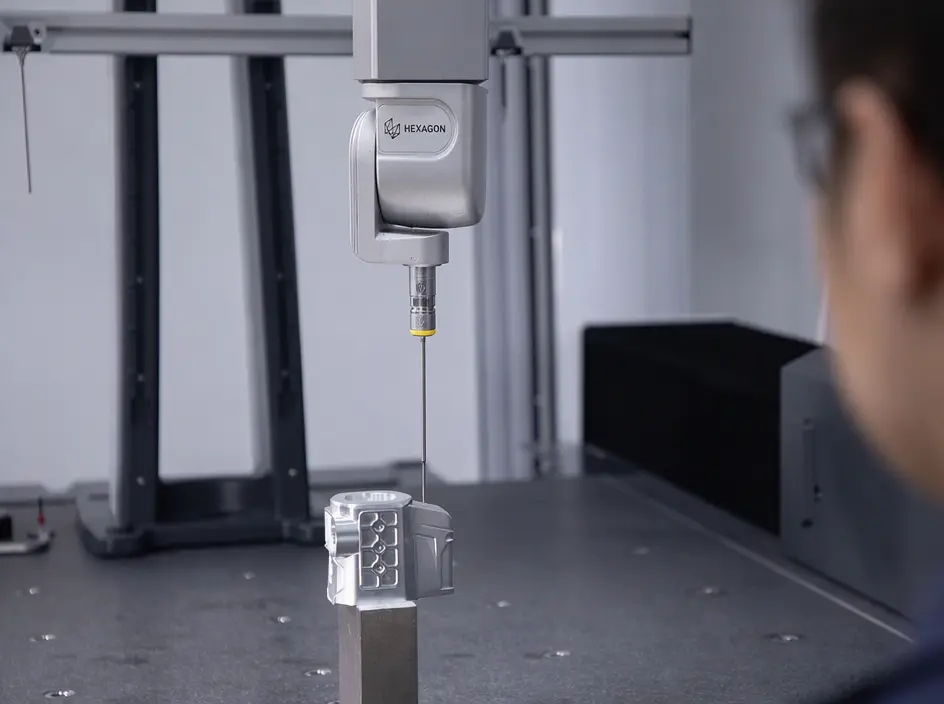
- Inspection: CMM scan, alloy spectroscopy, FAI per AS9102 Rev D. Report ships with the batch.
Process reference: YPMFG PBF-to-CNC route library, reviewed against published PBF tooling data. Client-specific parameters withheld per NDA.
Practical Questions Before You Specify a Process
Does 3D printing mean I skip all machining?
No. For aerospace, PBF produces the complex core; you still mill critical faces, tap threads, and grind seals. A fully as-printed flight part is rare outside of lattice and topology-optimized structures.
Can I use the same drawing for PBF and CNC?
Not without edits. PBF needs minimum feature callouts, orientation notes, and support-geometry flags. A Revisión DFM takes two to three days and catches most conflicts before the build file is released.
Is PBF cheaper at low volume?
Below 50 parts, PBF is often cheaper because there is no tooling setup. Above 200 parts, CNC unit cost drops below PBF because the build-and-heat-treat cycle dominates. The crossover depends on geometry and alloy.
What happens if the powder lot fails spectroscopy?
It cannot ship. The batch is scrapped and re-pulled. Your incoming spec should require a per-lot material certificate, not a one-time qualification. A bad lot in flight hardware means a ground program and a 90-day delay, not just a reprint.
Matching the Part to the Process
The core value of getting this call right is straightforward: you avoid a failed incoming inspection, a six-week rework cycle, or a certification gap that stalls a program. Geometry drives the process, not the other way around.
If you hold a drawing with mixed features—internal channels, tight bores, milled faces—send it to YPMFG for a free engineering review. The team will flag which faces need secondary CNC, which features need a tolerance upgrade, and which material lot to specify. You receive a one-page process map and a DFM note back within three business days.
When the part is ready, request a quote with the drawing and material spec attached. YPMFG will confirm build parameters, post-machining operations, and inspection scope before you commit to a batch.