Spanish
 English
 German
 Russian
 Japanese
 Korean
 French
 Italian
 Portuguese

Thread machining splits into three core routes: cutting, rolling, and grinding. Rolling produces threads up to 20% stronger than cut threads because plastic deformation aligns grain flow. The right choice depends on material hardness, thread diameter, and whether the part carries shear load.
Buying thread-machined parts means more than picking a tap size. The method you specify changes fatigue life, cycle time, tooling cost, and whether the thread holds on a stainless shaft under sustained vibration. A rolled thread on 6061 aluminum and a ground thread on 316L stainless solve the same fastening problem in very different ways. YPMFG works with engineering teams to match thread method to material, load case, and volume before metal moves. The sections below lay out that decision logic so you can spec with confidence.
- Thread rolling: Plastic deformation compresses the surface and aligns grain flow along the helix, raising fatigue life versus a cut thread on the same shaft.
- Material threshold: Rolling works below roughly 35 HRC. Harder stock requires thread grinding or cutting, which changes tooling and cycle time.
- Pilot hole geometry: An internal thread needs an undercut and a minimum pilot hole. Skipping the undercut creates a stress riser at the thread root.
- Clase de tolerancia: ASME Y14.5 thread callouts specify pitch diameter and major diameter. Match the pitch class to the fit, not just the nominal size.
Rolling wins on speed and strength for medium-diameter threads on softer stock. Grinding takes over the moment the part is heat-treated above 45 HRC, because the die can no longer deform the material.
Why Does Thread Method Change Fatigue Life?
The method changes how metal flows at the thread root. A cut thread removes material, leaving a sharp valley that acts as a crack starter under cyclic load. A rolled thread compresses the surface and aligns grain flow along the helix, which delays crack initiation by a measurable margin.

This matters most on shafts, bolts, and fasteners that see repeated shear or bending. A 6061 aluminum pin with a rolled M8 thread will outlast the same pin with a tapped thread in a vibration-heavy housing. Static clamp loads, however, are forgiving; a cut thread there performs adequately.
Three factors shift the outcome:
- Calidad del material: rolling suits stock below 35 HRC; harder material cracks the die.
- Thread diameter: below M3, rolling force becomes impractical on a 3-axis CNC.
- Load type: dynamic shear favors rolling; static preload tolerates cutting.
You cannot roll a thread on a part already hardened above 35 HRC. That combination exceeds die capacity and risks die fracture. For hardened parts, thread grinding is the only clean option.
When Does Rolling Beat Cutting, and When Does It Not?
Rolling beats cutting on cycle time and surface strength, but only within a material and size window. Above that window,the die either will not close or the part will not hold dimensional spec.
Rolling is a plastic-deformation process. Two hardened-steel dies compress the blank between them, and the thread forms without chip removal. Cycle time drops sharply compared with tapping because there is no chip evacuation. The surface also gains a compressive residual stress layer that resists crack propagation.
Cutting, by contrast, works on nearly any material hardness. A carbide tap on 316L stainless or a threading mill on H13 tool steel are standard. The trade-off is speed and the sharp root geometry that weakens the part under fatigue. For high-volume brackets in 5052 aluminum, rolling saves tooling wear. For a low-run hardened fixture in 4140, cutting or grinding is the only practical route.
YPMFG can review your drawing, material, and run quantity to flag whether a rolling die is justified or whether a CNC thread-milling operation is safer for the part. Sending the spec early avoids a costly die order that turns out to be unnecessary.
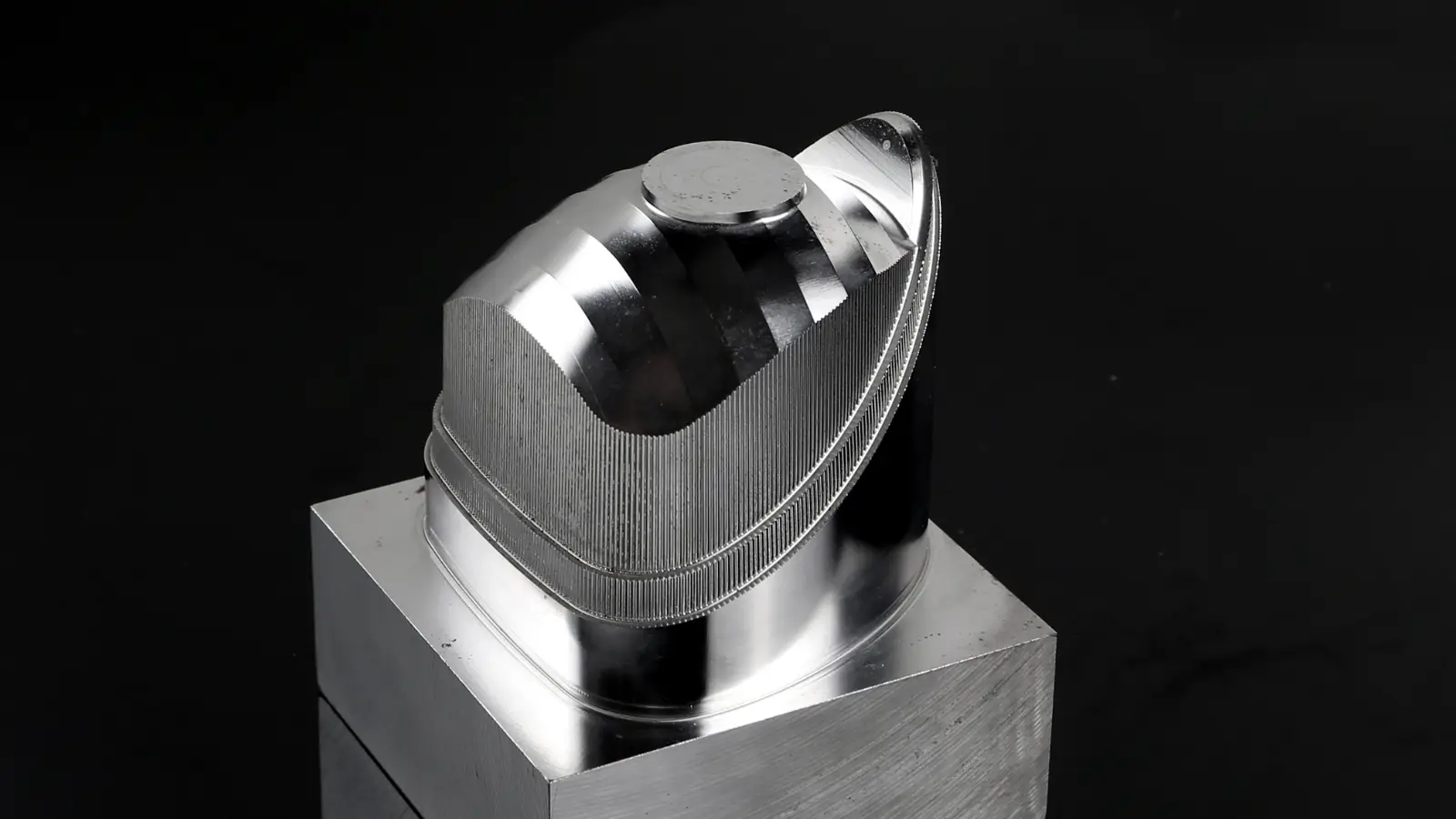
Rolling cannot produce threads below M3 on standard dies, and it will not work on material above 35 HRC without a dedicated high-pressure setup that changes the cost structure entirely.
How Do You Call Out Thread Tolerances on a Drawing?
The most common specification error is calling a thread by nominal size only. “M8 x 1.25” tells the shop the pitch, but not the fit. Without a pitch class, the machinist defaults to 6g or 6G, which may not match your assembly requirement.
ASME Y14.5 defines pitch class, major diameter tolerance, and thread depth. For internal threads you also specify the pilot hole diameter and undercut depth. A 0.5 mm undercut on a 10 mm pilot hole prevents the tap from bottoming out and galling the last partial thread.
Three checks before releasing a thread callout:
- State the pitch class (e.g., 6G for external, 6H for internal on general fit).
- Specify the thread depth and whether the last partial thread is broken.
- Cross-reference the CNC thread machining method against material hardness on the BOM.
A thread callout without a pitch class leaves the shop to guess, and a guessed fit on a pressure vessel flange is a liability. ISO 2768 general tolerances do not cover thread geometry; you must use the thread-specific standard.
How YPMFG Validates a Thread Before It Ships
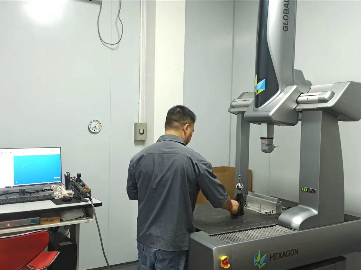
Thread features are verified at three stages, and the method changes what you inspect. On first article, we run a thread ring gauge or plug gauge against the specified pitch class and record the result. During production, a sampling plan checks pitch diameter and thread depth at defined intervals. The final report ships with the part, including gauge lot number and ambient temperature at measurement.
For rolled threads, we also verify surface hardness after the rolling pass. The compressive layer should sit in the outer 0.3 mm of the thread flank. If the hardness profile is flat, the rolling parameters were off and the fatigue benefit is lost. Grinding threads get a roughness check on the flank; a Ra above 1.6 µm on a ground thread signals a worn wheel and inconsistent contact.
If your part is IATF 16949 or ISO 13485 scoped, the thread verification data feeds directly into the PPAP or device file. YPMFG structures the inspection report to map to those audit requirements so your quality team does not have to reformat the package. Send the drawing and material spec, and the process route, gauge selection, and acceptance criteria come back as a single reference sheet.
Process Route Reference: YPMFG process library, reviewed against published tooling data. Client-specific measurement data withheld per NDA.
Practical Questions Before You Spec a Thread
Can I tap a thread on a 3D-printed nylon bracket? No. Standard carbide taps will glaze the nylon and strip the last two threads. Use a thread insert press-fit into a drilled hole, or design the bracket with a metal insert boss.
What is the smallest thread I can machine on a 3-axis CNC? M2 on a fine-pitch carbide tap, but below M2 the tap is brittle and the workholding geometry is tight. For M1 or smaller, micro-rolling or wire-EDM is the practical alternative.
Does a ground thread always beat a rolled thread on strength? Grinding gives the tightest dimensional control and a smooth flank, but rolling produces a stronger surface layer. For a load-bearing shaft below 35 HRC, rolling typically wins on fatigue. For a hardened raceway, grinding is the only option because the material will not deform.
How do I tell if my thread spec will survive a salt-spray test on 316L? The thread itself is not the corrosion path; the gap between mating threads is. Specify a sealed or coated thread (e.g., PTFE tape, thread lock) and verify the gap width on the 2D drawing. The salt-spray result depends on the seal, not the thread geometry.
Making a Better Long-Term Decision on Thread Method
Thread method is a one-way decision once the tooling is committed. A rolling die costs more upfront but drops per-part cost at volume above a few hundred pieces. A carbide tap is cheap to start but wears on stainless and needs replacement every few hundred cycles. Picking the wrong method now means rework, re-inspection, and a second die order later.
The core value is simple: match the deformation or cutting process to your material hardness, load case, and run quantity before you release the drawing. That single alignment prevents the most common field failures—galled threads, cracked roots, and out-of-tolerance pitch on a critical joint.
Send your specification, material, and target quantity to YPMFG for an engineering review. You will receive a recommended thread method, a pitch class, a pilot-hole and undercut callout, and a gauge plan for acceptance. No obligation, no waiting; the review typically turns around within 24 hours. If the part is IATF 16949 or ISO 13485 scoped, the review also maps to your audit checklist so the documentation package is audit-ready on the first pass.