Russian
 English
 German
 Japanese
 Korean
 Spanish
 French
 Italian
 Portuguese

A computing device aluminum heatsink is defined by three specs: base material grade (typically 6061 or 5052), fin density, and Обработка на станках с ЧПУ терпимость on the mounting interface. Most production runs hold ±0.05 mm on the base plane per ISO 2768. Get those three right and thermal performance follows.
Most engineering teams specifying a computing device aluminum heatsink hit the same wall: the datasheet lists a thermal resistance target, but the drawing does not say which fin thickness, base thickness, or surface finish actually delivers it. Vendors quote a part number and a lead time, yet the critical decision—whether to machine or die-cast, which alloy, and what tolerance on the mounting holes—stays undocumented. YPMFG works with OEM and server builders to close that gap before the first batch ships.
Key Takeaways
- Марка материала: 6061-T6 gives higher yield strength for fin integrity; 5052 offers better fatigue life for vibration-heavy enclosures. Pick based on the device’s operational environment.
- Process choice: CNC 3-axis machining handles fin features down to 0.4 mm web thickness; below that, consider 5-осевой ЧПУ or micro-milling to avoid chip clogging.
- Tolerance criticality: Mounting interface flatness at 0.02 mm per ASME Y14.5 prevents thermal pad compression failure in sustained load scenarios.
CNC Machined vs. Die-Cast Aluminum Heatsink: Where Each Makes Sense
The decision comes down to fin geometry complexity and production volume. Machined parts hold tighter tolerances on the mounting face; cast parts win on per-unit cost at scale.
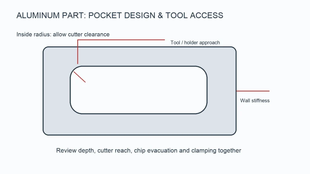
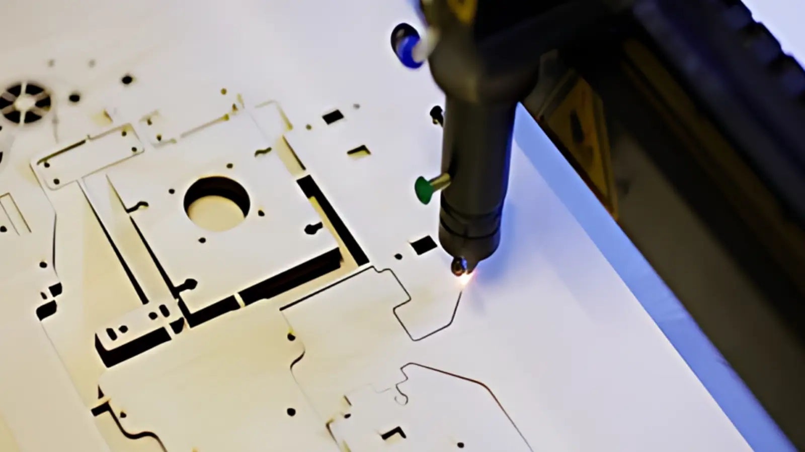
A 3-axis CNC route machines each fin from a 6061 block. Tooling cost stays low, and a 3-day sample is achievable. The limit: fin webs thinner than 0.4 mm risk breaking under clamping force. A 5-axis setup handles undercut fins and angled heat pipes that a 3-axis tool cannot reach without re-fixturing.

Die casting produces the whole fin array in one shot. Cycle time drops to seconds per part, which matters above a few thousand units. The trade-off: gate marks and porosity require an additional die-cast finishing pass, and the mold tooling amortizes only past a certain volume threshold.
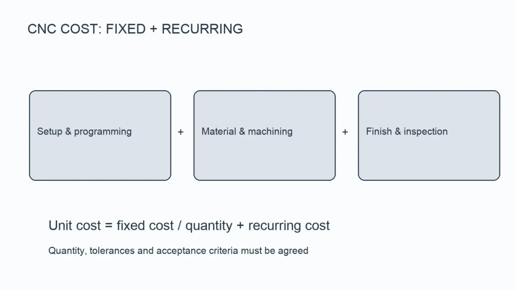
Below the 5,000-unit mark, the mold cost rarely justifies a cast tool. Send your BOM quantity to YPMFG and the team will run a break-even comparison against your target price point.
How Does Fin Geometry Affect Thermal Performance in a Small Enclosure?
Fin density is not a free variable. Pack too many fins and airflow chokes; pack too few and you lose surface area. The sweet spot depends on the fan curve in your specific enclosure.
For a computing device under 100 W with forced airflow, fin spacing of 2–3 mm and a height of 12–18 mm typically balances ΔT against pressure drop. Below 2 mm spacing, the boundary layers on adjacent fins merge and heat transfer per fin drops. Above 18 mm height, tip-to-base ΔT grows and the top fin contributes little.
The base thickness matters as much as the fins. A 3 mm 6061 base spreads point loads from the CPU or GPU die across the entire fin array. Below 2 mm, the base flexes under socket pressure and creates an air gap at the thermal interface.
One physical limit: no fin geometry compensates for a contaminated or misaligned thermal pad. You can machine perfect fins, but if the assembly process lets the interface shift by 0.5 mm, the cold spot on the die goes unmanaged. This is a process control question, not a machining question.
What Tolerance and Surface Finish Should You Hold for Mounting Interfaces?
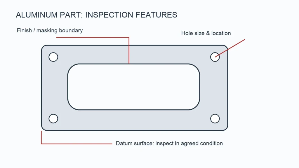
The mounting face is the single most critical surface on the part. A 0.1 mm warpage there translates directly into non-uniform pressure on the thermal pad and a measurable Rθ rise.
Hold the base plane to 0.02 mm flatness. Call it out as a specific feature control frame per ASME Y14.5, not just “true to B.” For through-holes that accept standoffs, a допуск при обработке на станках с ЧПУ of ±0.05 mm on diameter and ±0.02 mm on position keeps assembly simple without requiring reaming.
Surface finish on the base: 3.2 μm Ra is the common spec. Rougher than that and the thermal interface material cannot wet the surface, leaving trapped air. Smoother (1.6 μm) adds machining time and is rarely justified unless you are running a vacuum-flush assembly line.
Side and top surfaces can relax to ISO 2768-mK. Call this out explicitly on the drawing so the shop does not machine the fin tops to 3.2 μm Ra and inflate your cost with no thermal benefit.
How a CNC Heatsink Process Route Handles a Typical GPU Cooler
A GPU class heatsink—roughly 90 × 60 × 15 mm, 6061-T6, 2.5 mm base, 14 fins at 2.5 mm spacing—follows a repeatable route that balances throughput and quality.
- Block prep: Saw a 6061 plate to 92 × 62 × 16 mm. Deburr. Verify material cert (mill TDS) matches 6061-T6.
- Base machining: 3-axis CNC, face-mill the mounting plane to 0.02 mm flatness. Drill four M3 clearance holes at ±0.05 mm positional tolerance.
- Fin pass: Same setup, plunge-mill 14 slots. Use an 8 mm carbide end mill with a 0.4 mm slot bottom to preserve web strength. Chip evacuation at 15 L/min.
- Edge break: 0.5 mm chamfer on top and side edges to prevent handling injury and reduce stress concentration.
- Surface pass: Mill the base to 3.2 μm Ra. Leave fin tops at 12.5 μm Ra.
Key control points: verify fin parallelism at 0.03 mm across the 60 mm span after the fin pass. A tilt beyond that creates a shorter fin on one side, reducing effective area by up to 10 percent on that corner.
Process Route Reference: YPMFG process library, reviewed against published tooling data. Client-specific batch data withheld per NDA.
Practical Questions Before Specifying an Aluminum Heatsink
Can die-cast fins replace machined fins at any volume? No. Below 0.8 mm web thickness, the casting gate will not fill a 0.4 mm channel cleanly. If your thermal design demands webs under 0.8 mm, machining is the only viable route.
What is the practical limit of fin count on a 90 mm wide part? At 2.5 mm spacing you fit roughly 35 fins. Push to 1.5 mm spacing and airflow resistance climbs faster than surface area gain. The limit is aerodynamic, not mechanical.
Does anodizing improve thermal performance? It adds 10–25 μm of oxide, which is a tiny insulating layer. The gain in corrosion resistance for consumer enclosures far outweighs the marginal Rθ cost. Specify type II anodize, 15 μm, for a good balance.
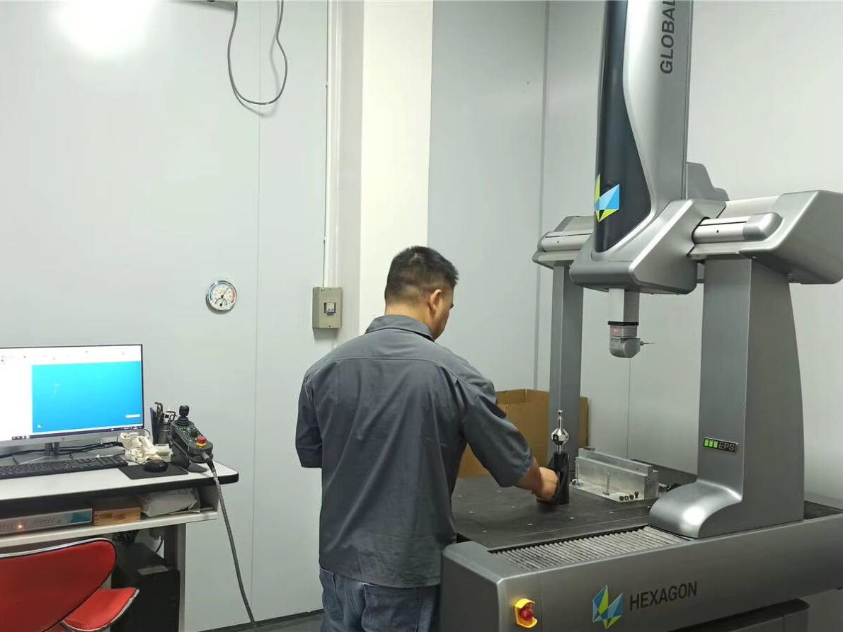
How do I validate a first article before releasing the batch? Попросите первичный контроль продукции report covering 100 percent of critical dimensions, a material cert, and a flatness check on the base. Hold one unit as the batch reference. YPMFG includes this as standard on production orders.
Making a Better Long-Term Decision on Heatsink Sourcing
The most expensive mistake is not the part itself but the revision cycle that follows a poor initial spec. Three weeks of rework on fin spacing or hole pattern costs more than the margin difference between vendors.
Start by sending your thermal target (ΔT per watt at a specified airflow) and the mechanical envelope to YPMFG. The engineering team will suggest a material grade, a fin layout within your envelope, and the minimum volume where die-cast economics kick in. You get a one-page feasibility summary with process options, lead times (3-day sample, 20–25 days for production), and the documentation set your QA team will need at receiving.
You will not get a guaranteed thermal number on paper before the first article is built and tested on your actual board. What you will get is a drawing that matches your spec exactly, a process that can hold it, and a supplier who flags the risk before it becomes a rework order. That is the part most buyers discover they needed on the second or third RFQ.