English
 German
 Russian
 Japanese
 Korean
 Spanish
 French
 Italian
 Portuguese

Aerospace milling differs from general CNC in three ways: tighter CNC machining tolerance specs (often 0.01 mm on critical features), significantly slower material removal in titanium or Inconel compared to 6061 aluminum, and full traceability inspection per AS9100. Lock in material, tooling, and inspection plan before you fix a delivery date.
You are probably comparing quotes on a titanium bracket or an Inconel housing and wondering why one shop runs 40 percent slower than another. The gap sits in material cutting strategy, aerospace milling tolerance stack-up, and inspection depth. YPMFG reviews incoming prints against these three levers so schedule risk is visible before the first chip flies.
Key takeaways at a glance:
- Material removal rate: Titanium and Inconel cut far slower than 6061 aluminum, so cycle estimates for nickel or titanium parts will look very different from your aluminum baseline.
- Tolerance stack-up: Aerospace prints often call for 0.01 mm on critical bores; verify every GD&T symbol before accepting a quote.
- Traceability: AS9100 requires material certs, tooling records, and inspection data to travel with the part. Missing one document can stall delivery at the integrator.
Routing choice matters more than machine brand. The table below summarizes where each axis count earns its keep.
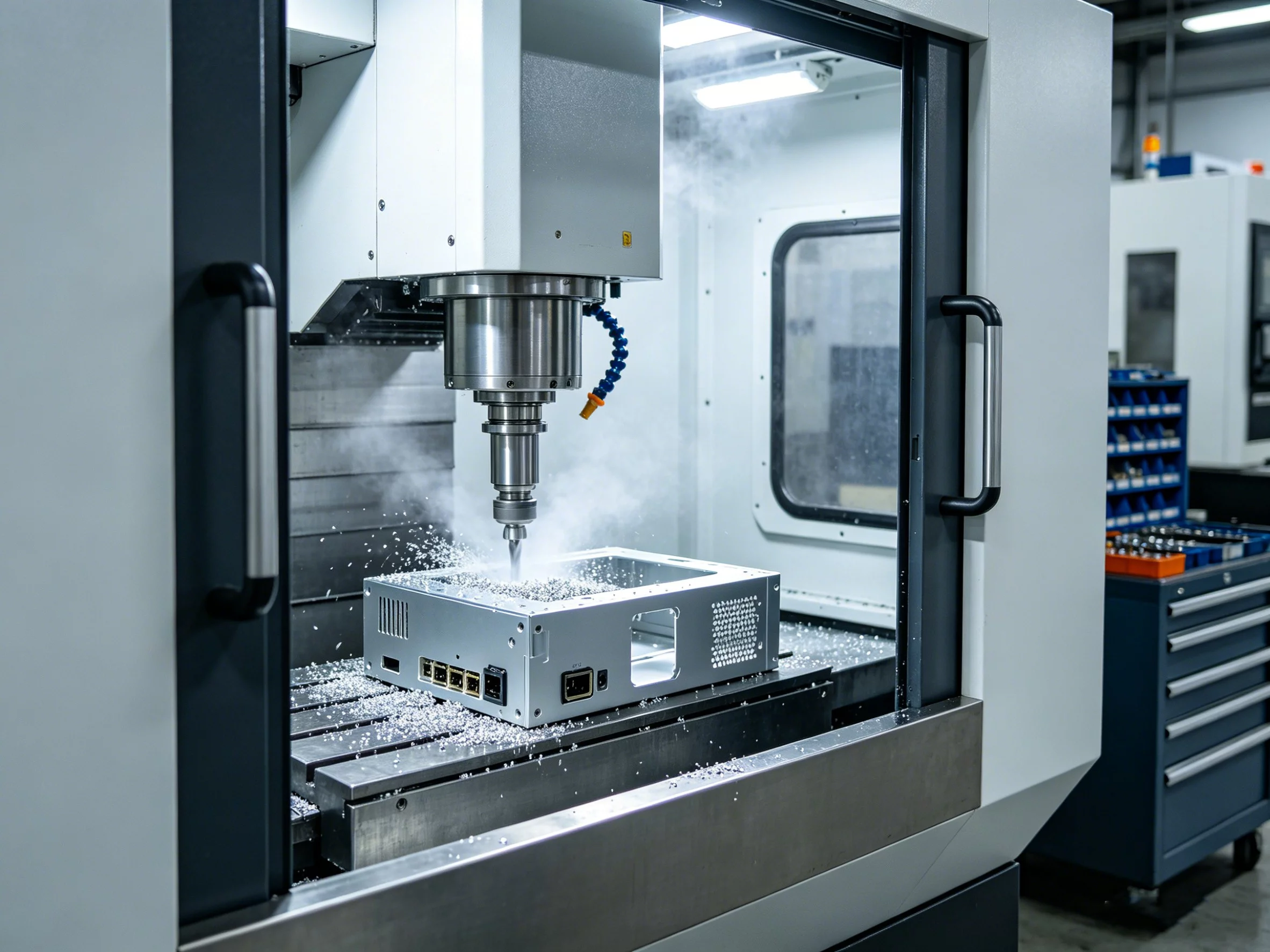
When your part carries more than two oriented surfaces and a stack under 0.02 mm, a 5-axis CNC route typically saves one setup and a CMM re-clamp cycle.
Figure: 3-axis vs. 5-axis routing comparison for aerospace milled components.
What Makes Aerospace Milling Different from General CNC?
The label “aerospace” changes the cutting strategy and the paperwork trail, not just the marketing folder. Three variables shift: material hardness, tolerance depth, and the inspection record that must ship with every part.
Material and Cutting Strategy
Titanium alloys and Inconel families may require feed rates well below what you run on 6061 aluminum. Chip load set too high on titanium work-hardens the surface and forces a second pass. The right cutting envelope depends on the specific alloy grade and heat treatment condition listed on your print.
The physical limit is clear: you cannot cut Inconel at aluminum speeds and expect the tool to survive. Accept longer cycle times, or switch to a lower-alloy alternative if the function permits.
Which Tolerances and Materials Drive Your Cost?
Tolerance is the single biggest cost lever in aerospace work. A 0.1 mm callout on a non-critical face adds little. The same 0.01 mm on a sealing bore changes fixture design, inspection method, and scrap risk.
Tolerance Stack in Practice
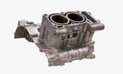
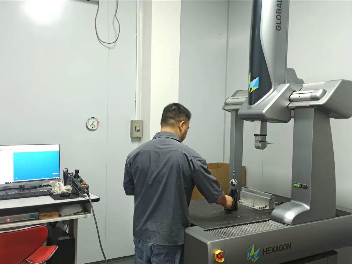
ASME Y14.5 governs how GD&T symbols translate into measurable limits. A profile or position callout on a finished surface often requires a CMM scan rather than a micrometer. Over-tightening non-critical features wastes inspection hours; under-tightening critical ones risks rejection at final acceptance.
Walk your print feature by feature and flag which dimensions are truly functional. The boundary: thermal growth during the cut means you program a temperature-compensated offset; you cannot eliminate it, only control it within a defined envelope.
Inspection, Traceability, and What to Send
AS9100 compliance (built on ISO 9001) requires a full paper trail: material heat number,tooling lot, operator log, and inspection report. A missing cert stalls delivery at the integrator even if the part is dimensionally perfect.
A Typical Process Route
Most aerospace milled parts follow this sequence: raw stock verification against material cert, roughing at reduced feed for the alloy, semi-finishing to leave 0.1 mm stock, finishing within first article inspection tolerance, CMM scan, deburr, and pack. Each step logs its parameters. If a part fails, the record pinpoints which tool or feed setting caused the deviation.
Process Route Reference: YPMFG process library, reviewed against published tooling data. Client-specific data withheld per NDA.
Before requesting a quote, send four items: a 3D model in STEP or IGES, a 2D drawing with all callouts, the material grade with AMS spec, and your acceptance standard. Without the acceptance standard, the shop guesses inspection depth and you inherit the rework risk.
Common Questions About Aerospace Milling
Can any CNC shop handle aerospace milling?
No. The machine must be calibrated, the operator trained on the specific alloy, and the shop must hold AS9100 or an equivalent certification. A general shop running 6061 all day has not qualified for a titanium engine bracket.
How tight can aerospace milling tolerance get?
It can hold 0.005 mm on critical features, but that level demands a dedicated fixture, a CMM scan, and a slower finishing pass. It cannot be guaranteed in a single rough-and-finish cycle on Inconel.
What kills a schedule most often?
Material. A late heat lot or a failed incoming inspection on a titanium billet pauses the entire job. Confirm your material source lead time before you lock a delivery date.
Do I need a new FAI for small design tweaks?
Often, yes. Even a 0.05 mm change to a critical dimension may require a supplemental FAI. Check with your program manager before assuming the old report still covers the revision.
Making the Right Call on Your Next Aerospace Part
The three decisions that save the most money are material selection, tolerance triage, and inspection depth. Get those three right and the rest is execution. Send your drawings, material specs, and acceptance criteria to YPMFG, and an engineer will walk you through a DFM review, flag tolerance risks, and quote a realistic schedule. No commitment required—just a clear picture of what your part actually needs.