Portuguese
 English
 German
 Russian
 Japanese
 Korean
 Spanish
 French
 Italian

Custom automation equipment parts typically demand tighter positional tolerances, consistent acabamento da superfície, e certificação de materiais that a standard bracket job does not. Most buyers lose two or three revision cycles because they send a 2D PDF with implied tolerances instead of a 3D model with an ASME Y14.5 datum scheme. The single biggest time-saver: send a 3D STEP file with explicit feature control frames and cut your quote-to-production lead time roughly in half.
Buying machined components for an automation line is not the same as ordering a housing or a frame. You are sourcing parts that load, move, and interface with pneumatics, sensors, and other machined surfaces on a gantry or pick-and-place head. One missed tolerance on a shaft seat and the whole axis wobbles. YPMFG works with integrators and OEMs who need custom automation equipment parts that hold dimensional stability across long production runs. The sections below walk through the specs, material choices, and process decisions that actually matter when your part spends 16 hours a day inside a running machine.
- Acúmulo de tolerâncias: A 0.05 mm shaft-to-bore clearance suits low-speed automation; below 0.02 mm you typically need honing or grinding, which adds a second process and cost.
- Tipo de material: 6061-T6 handles most structural frames; 304 stainless wins where washdown or corrosion occurs; H13 tool steel is reserved for die-facing contact surfaces.
- Drawing completeness: A 3D STEP file with ASME Y14.5 datums cuts quote-to-production lead time by roughly 50 percent compared to a 2D PDF with implied tolerances.
Which Machining Route Fits Your Automation Part?
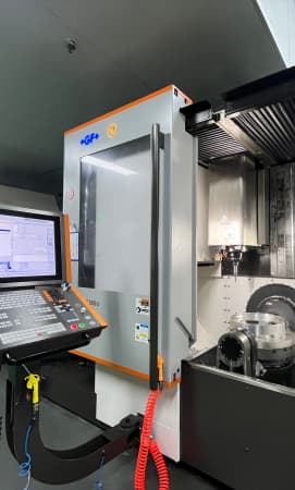
The first decision is whether your part is prismatic or multi-angled. A simple base plate, shaft, or flange routes to a 3-axis CNC mill or lathe in most cases. The moment your geometry has undercuts, compound angles, or a form that only clears a 5-axis tool path, the route changes. Choosing the wrong machine adds setup time without improving accuracy.
If your part is a clean prismatic shape in aluminum or mild steel, 3-axis is the right answer and the cost per piece stays low. A 5-axis route is not simply “faster”; it buys you the ability to machine five faces in one clamp, which protects acúmulo de tolerâncias across mating surfaces. The physical limit: even a 5-axis head cannot reach a pocket deeper than the tool’s own shank diameter allows. Beyond that depth, you need a deep-milling tool or a separate EDM operation.

Which Material and Heat-Treatment Route Fits Your Application?
Material choice drives more cost and performance variation than machine selection. For structural frames and motion platforms, 6061-T6 offers a good strength-to-weight ratio and machines well at standard feeds. Where your part sees washdown fluids, marine exposure, or chemical contact, 304 or 316L stainless is the safer call. If a surface contacts a die, a cam, or a high-wear interface, H13 tool steel in the 42–46 HRC range is the typical specification.
The heat-treatment step matters as much as the alloy. A 6061 part that skips the T6 aging cycle will not meet the published 276 MPa tensile value from the ASTM B209 datasheet, and your frame will deflect more than the drawing allows. When you request material, ask for a mill certificate traceable to a specific heat number. YPMFG can help buyers compare alloy grades against their load and cycle-life requirements before you lock a material call into the BOM.
One limit to acknowledge: stainless steel machines at roughly one-third the chip speed of aluminum. A part that takes 2 hours in 6061 can take 6 hours in 316L. That time difference flows directly into cost and lead, so do not default to stainless out of habit if the application tolerates it.
How Do Tolerance and Surface Finish Drive Both Cost and Function?
Tolerance is where most automation part budgets are quietly lost. A 0.1 mm positional tolerance on a sensor mount costs almost nothing extra. The same 0.1 mm called on a bearing seat where you actually need 0.02 mm will trigger a secondary grinding or lapping step, and the part price can double. Before you tighten a number on the drawing, check whether the function actually requires it.
Surface finish follows the same logic. An Ra of 3.2 µm on a structural face is standard mill finish and adds no cost. An Ra of 0.8 µm on the same face means a finishing pass with a smaller tool and lower feed, which lengthens cycle time and wears the insert faster. For sealing or bearing interfaces, specify the finish on the mating face only, not the entire part.
The professional check: open your drawing, highlight every tolerance and finish callout, and ask “what breaks if this number loosens by 0.05 mm?” If nothing breaks, loosen it. YPMFG engineering review can flag over-specified callouts before the quote is generated, which protects your budget without sacrificing function. The physical limit: no cutting process can hold below roughly 0.005 mm on a large flat face. Below that, you are into precision grinding or lapping territory, which changes the process entirely.
What Should Your Drawing Package Include Before You Send It for a Quote?
A complete package saves you a round of back-and-forth email. At minimum, you need a 3D CAD file in STEP or IGES format, a 2D drawing with chamadas GD&T following ASME Y14.5, a material specification with minimum heat treatment, and a quantity range. If your part feeds a safety-critical or regulated system, include the applicable standard, whether that is ISO 13485 for medical or IATF 16949 for automotive-adjacent automation.
- Datum scheme: Define primary, secondary, and tertiary datums on the 2D drawing. Without them, the shop will assume its own reference and your part will not sit in the assembly.
- Quantity range: Give a realistic floor and ceiling. A part quoted at 5 pieces will use a different tooling and setup strategy than the same part at 500.
- Inspection criteria: State whether you need a CMM report, a CMM verification at first article, or both, and which dimensions trigger the check.
You can send your specifications to YPMFG for a no-obligation engineering review before you commit to a supplier. The team will flag missing datums, over-specified finishes, and material mismatches in one pass. The honest limit: no drawing package can replace a physical first-article inspection for a new part. Plan for that step in your timeline.
How a Typical Automation Part Moves Through CNC Machining: A Process Route
Take a 6061-T6 linear rail base with four mounting holes, two shaft bores, and a flat top surface. The route looks like this:
- Blank and clamp: Saw a 2D billet with 10 mm machining allowance on all faces. Clamp in a vise with a 0.05 mm dial indicator check on the reference face.
- Rough mill, 3-axis: Remove bulk material with an 80 mm carbide end mill at a feed that keeps chip thickness above 0.15 mm per tooth. Target 2 mm stock on all faces for the finish pass.
- Finish mill: Switch to a 20 mm mill, drop feed by half, and hit the final contour and the top-face Ra of 3.2 µm.
- Bore and drill: Run the two shaft bores with a coolant-flushed drill, then ream to final diameter. The ream step is what gets you into ±0.01 mm on bore diameter.
- Deburr and verify: Manual deburr,wash, and run a first-article CMM check against the ASME Y14.5 callouts.
Process Route Reference: YPMFG process library, reviewed against published tooling data. Client-specific cycle times and tool wear data withheld per NDA.
Practical Questions Before Ordering Custom Automation Parts
Can I just send a screenshot of my CAD file? No. A screenshot carries no geometry data. Send a STEP or IGES file; a flat image will not reproduce your 3D features or your tolerance callouts.
What is the smallest batch you will machine? Depending on the part size and material, a single prototype is feasible. The economics improve sharply once you reach a batch of 10 or more, because setup amortizes across pieces.
Do you inspect every part or just the first article? Standard practice is a full CMM first-article report, then in-process sampling on each subsequent batch. If your application demands 100 percent dimensional screening, that is a separate inspection line and a separate cost.
Can I switch from 6061 to 5052 mid-production without re-qualifying? It cannot be treated as a drop-in. 5052 has a lower yield strength than 6061-T6, so your frame deflection will change. Re-check the load calculations and get written sign-off before the switch.
Choosing the Right Process for Your Automation Parts
The right combination of machine route, material grade, tolerance callout, and inspection plan is what separates a part that runs for years from one that scrapes its bearing seat in a month. The starting point is always a clean drawing package and a frank conversation about load, cycle count, and environment. YPMFG engineering can review your specification set, flag over-specified or under-specified callouts, and recommend the shortest process route that still meets your function. Send your STEP file, 2D drawing, and quantity range for a written quote and an engineering assessment. No obligation, no minimum project size. What you get back is a line-item cost breakdown, a recommended material and heat-treatment grade, and a clear inspection plan you can attach to your incoming-requirements document.