French
 English
 German
 Russian
 Japanese
 Korean
 Spanish
 Italian
 Portuguese

A CNC machined heat sink moves heat from the die through the base and out through fins into moving air. The spec that decides success or failure is fin density matched to available airflow, not the largest surface area you can carve.
Most heat sink failures in the field trace to one root cause: the machining geometry was set without tying it to the actual thermal load. Oversized fins choke airflow. A slightly warped base face adds thermal resistance no fin array can compensate for. YPMFG works with electronics and power-systems buyers to align CNC machined heat sinks geometry, material, and surface finish to the real thermal budget before the first part leaves the shop.
- Thermal conductivity: Aluminum 6061 conducts about 201 W/m·K; copper reaches 380 W/m·K. Select on weight, cost, and mounting clearance, not the highest number on the datasheet.
- Fin density versus airflow: Past a certain fins-per-inch count, the pressure drop exceeds the fan curve and the sink runs hotter than a sparser design.
- Base-face flatness: A 0.05 mm deviation over a 50 mm span adds measurable thermal resistance that extra fin area cannot offset.
Which Machining Route Fits Your Heat Sink?
Three-axis machining covers most standard finned heat sinks at a lower per-unit cost. Five-axis earns its place when fin angles wrap around the part or when the base and fins must hold Tolérance d'usinage CNC in a single clamping operation.

What Material Sets Your Thermal Ceiling?
The base plate material sets the upper limit on how fast heat leaves the die. Aluminum 6061 and 5052 remain the default for most consumer and industrial heatsinks because they balance conductivity, weight, and cost. Copper pushes conductivity up but doubles material cost and adds weight that affects mounting.
For power electronics above 200 W, the thermal path through the base dominates. A 2 mm thick 6061 base plate gives a manageable thermal resistance; thinning it to 1 mm raises that resistance by roughly the same factor. YPMFG can run a quick thermal-resistance estimate if you send the die size, power dissipation, and max ambient temperature with your heat sink base plate drawing.
Brass and copper variants suit RF and aerospace applications where vibration damping or corrosion resistance matters more than peak conductivity. The trade-off is density: copper runs about 8.9 g/cm³ versus 2.7 for 6061, which changes the mounting hardware spec. The physical limit here is that no machining process can make the base thinner than the tool can hold rigid without deflection, so very thin, wide plates need a different structural approach.
How Do Fin Geometry and Airflow Interact?
More fins mean more surface area, but each fin also blocks the air that carries heat away. The heat sink profile that performs well is the one where fin spacing matches the static pressure of the fan or natural convection in the enclosure, not the densest array you can machine.
A practical starting point: for forced-convection designs using a 25 mm fan, fin spacing between 4 and 6 mm per fin pair keeps pressure drop within the fan curve. Below 3 mm, the fan stalls in mass flow and the sink temperature climbs despite the extra metal. Natural-convection designs need wider spacing, often 8 mm or more, because buoyancy-driven flow is far slower than fan-driven flow.
Angled or split fins break up the thermal boundary layer and can lower the effective thermal resistance by 10 to 15 percent at the same footprint. The cost is that angled fins push the part into five-axis territory or require flip-and-rework on a three-axis machine. You can send your heat sink profile sketch to YPMFG for a DFM review before committing to a tool path.
Which Tolerance Should You Hold on the Base Face?
The base face is the thermal interface, and a flatness deviation of even 0.05 mm creates a gap that behaves like a thermal insulator. For die-attach applications, holding ISO 2768-mK flatness on the base is the minimum. For high-power or vibration-priced environments, specify flatness at 0.01 mm over the contact diameter on the drawing.
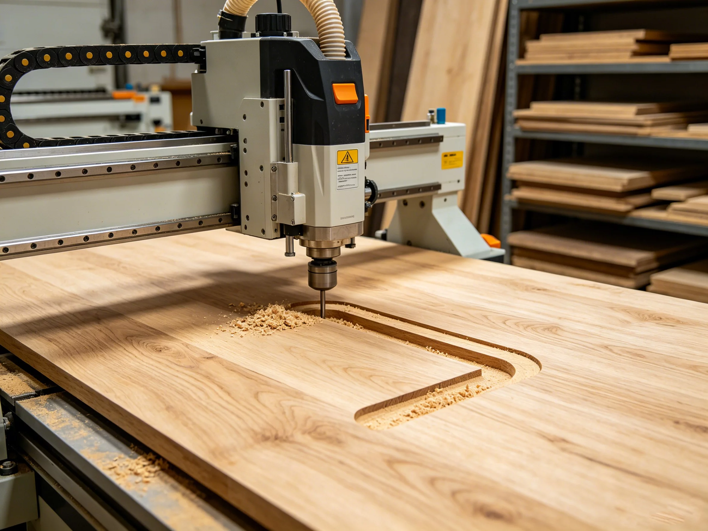
Material choice interacts here. Copper and brass are softer than 6061; the base face will bow slightly during clamping if the part is thin. A five-axis single-setup hold removes the clamping-induced bow. On a three-axis setup with two flips, the second operation can introduce a shift that adds 0.02 mm of deviation. YPMFG flags this in the DFM notes when the wall-to-thickness ratio drops below 2:1.
The honest limit: a machined surface, no matter how fine the toolpath, leaves micro-valleys. Those valleys trap air at the die-sink interface and add a thin, high-resistance layer. The fix is not tighter machining; it is a proper thermal interface material matched to the gap size. The machine can only guarantee the flatness spec on the drawing.
When Does An Anodized Finish Actually Help?
Un anodized finish on an aluminum heat sink does two things: it raises corrosion resistance and it lets you add a thin dielectric layer if the fins sit near grounded components. Thermally, a Type III anodize at 10 to 20 µm adds a marginal resistance increase that is negligible for most loads above 10 W.
For high-power or RF applications, skip the anodize on the fin faces and limit the coating to the base and mounting edges. The uncoated fins expose bare 6061 to the airflow, keeping the thermal path clean. YPMFG can mill the fins first, then mask and anodize only the exposed faces, which keeps the finish consistent across a batch.
Copper and brass heat sinks are typically protected with a nickel or gold plating rather than an anodize, because those metals do not anodize in a meaningful way. The plating thickness and adhesion spec matter more than the base metal choice for long-term thermal stability. The physical constraint: no surface treatment can substitute for proper fin geometry and airflow. A poorly spaced fin array will underperform even with a perfect finish.
How a Standard CNC Heat Sink Moves from Print to Part
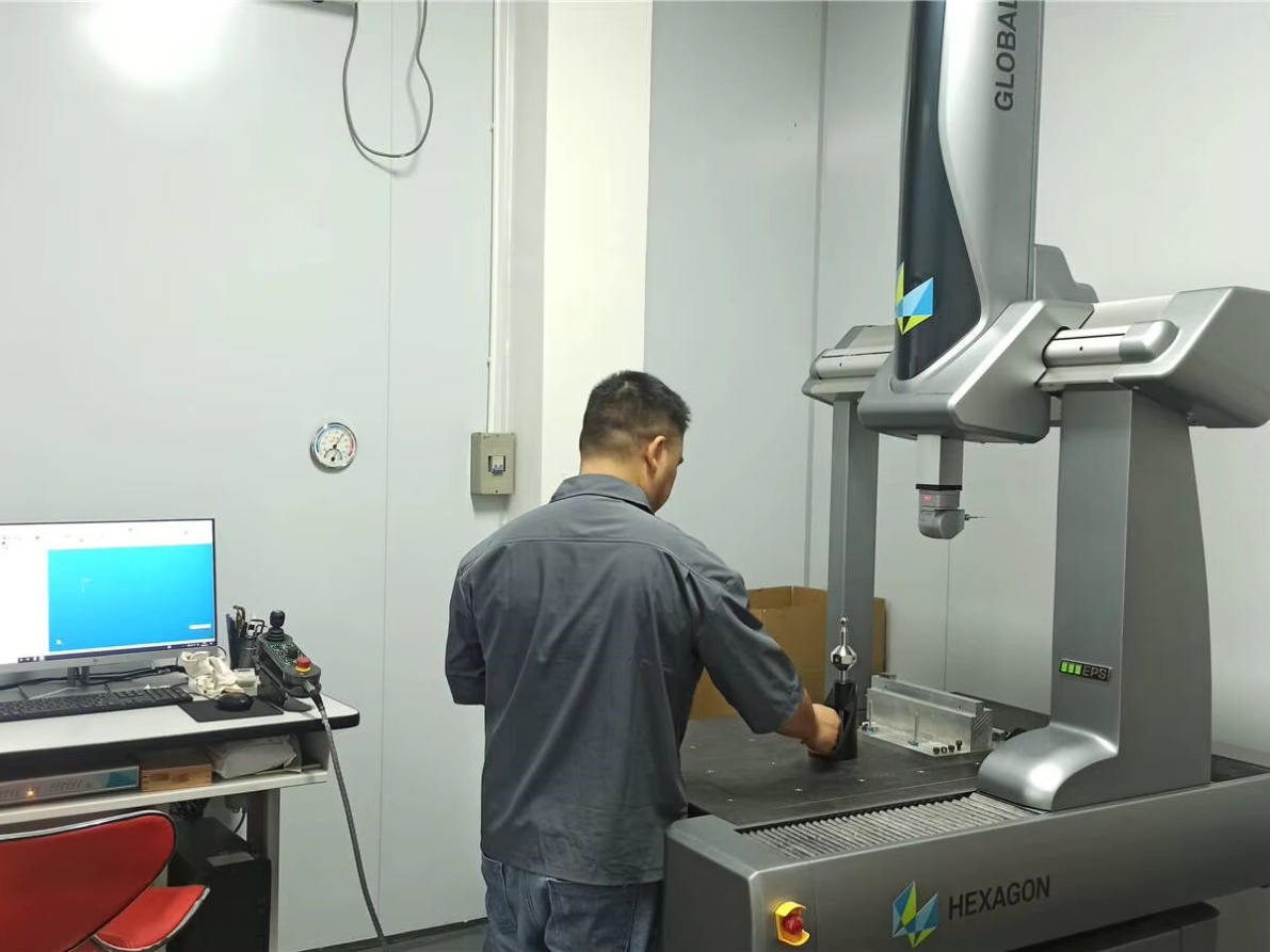
A typical 6061 finned heat sink follows a short route: rough mill the billet to 0.5 mm oversize on all faces, flip and run the fin array with an end mill at 0.1 mm stepover, then back-mill the base to final flatness in one setup. Each step is controlled by in-process probes on the tooling path, and the final part goes through a CMM check against the drawing before it leaves the machine.
For angled-fin or conformal geometries, the part stays in a five-axis vise through roughing and finishing,eliminating the flip-and-rework shift. The critical control point is the clamping interface on the base face: soft jaws protect the finish and keep the part from bowing. YPMFG reviews the clamping plan in the DFM pass and flags any risk of jaw marks on the mating surface.
Common failure modes at this stage include chipping on thin fins during tool retraction and burr buildup at the fin root that traps coolant. Both are caught by the in-cycle inspection. The route reference below covers the standard process; client-specific parameters are withheld per NDA.
Process Route Reference: YPMFG process library, reviewed against published tooling data. Client-specific parameters withheld per NDA.
Practical Questions Before You Spec a Machined Heat Sink
Can I use the same heat sink for both natural and forced convection? No. A fin array sized for natural convection will choke a fan and overheat the enclosure. A fin array sized for a fan will be marginal or useless with still air. Pick the regime first, then size the fins.
What is the thinnest fin a CNC mill can hold without deflection? It depends on the material and the fin depth. In 6061, a fin under roughly 0.8 mm wide and 15 mm deep will chatter or deflect during cutting. For finer fins, you need EDM or a different thermal design. The machine has a physical rigidity floor.
How much does copper cost versus 6061 for the same part? Copper billet runs about two to three times the raw material cost of 6061, and the slower cutting speeds add machine-hour cost. Depending on the part size, the finished copper sink may run 40 to 80 percent above the aluminum equivalent.
Can I get a flatness tighter than the drawing says without rework? It depends on the clamping and tooling. If the drawing calls for 0.02 mm and the part needs 0.005 mm, that is a different machining strategy, not just a tighter post-inspection. YPMFG flags this in the DFM review before the first cut.
Choosing the Right Machined Heat Sink for Your Load
The decision is not about the most fins or the shiniest finish. It is about matching three numbers: the die power, the ambient and enclosure airflow, and the maximum allowable junction temperature. Get those three right and the geometry follows. Get them wrong and no material upgrade will save the design.
YPMFG reviews thermal budgets alongside the mechanical drawing before quoting. Send your specifications, the die thermal data, and the enclosure airflow profile to YPMFG for an engineering review. The team will return a DFM note, a suggested fin layout, and a material recommendation tied to your actual thermal load, so the next iteration is the one that ships.