French
 English
 German
 Russian
 Japanese
 Korean
 Spanish
 Italian
 Portuguese

A CNC milled wheel typically holds radial runout under 0.05 mm and concentricity within 0.03 mm on a 24-hour press fit. Start with your ISO 2768 tolerance class before specifying material.
You are specifying a milled wheel and wondering which tolerance class, material grade, and machining sequence actually hold up in service. The wrong call shows up as premature bearing wear, vibration at speed, or a part that fails its first assembly fit. YPMFG engineers review wheel drawings against published tooling data before quoting, so the numbers below reflect what is achievable in standard Fraisage CNC without exotic setups.
- Radial runout: Target 0.03 to 0.05 mm for rotating wheels above 3000 rpm; tighter classes add 2 to 3 hours of machining.
- Nuance de matériau: 6061-T6 handles most structural wheels; 316L is required when corrosion exposure exceeds 10% salt-spray hours.
- Classe de tolérance: ISO 2768-m is the default for general wheels; step to ISO 2768-k when mating surfaces have a 0.02 mm fit gap.
- Cost driver: A 5-axis finishing pass on a 200 mm diameter wheel adds roughly 40% to a 3-axis route.
Pick the material that matches your worst-case operating condition, not the average. A wheel that sees a brief rain exposure but must show zero visible pitting after 5 years still needs 316L.
What Tolerance Should a CNC Milled Wheel Hold?
The tolerance you need depends on rotating speed, load type, and mating fit. Most buyers over-specify because the drawing template defaults to the tightest class.
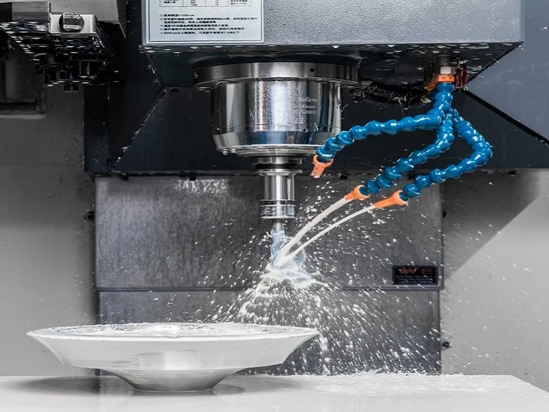
Radial runout is the first number to lock. For a wheel turning above 3000 rpm, 0.03 mm keeps vibration within acceptable limits for most bearing assemblies. Below 2000 rpm, 0.05 mm is typically sufficient. Fraisage CNC on a 3-axis machine holds these values once the workpiece is clamped in a 4-jaw chuck with a center-hole alignment check.
If the wheel is not paired with a hydraulic bearing or thin-film seal, ISO 2768-m is enough. Save the k-class budget for surfaces that mate with a 0.02 mm gap.
One physical limit: a milled 90-degree inner corner on a wheel bore leaves a small radius equal to half the tool diameter. A 6 mm end mill leaves a 3 mm radius. If your drawing calls for a sharp corner, plan for EDM or broaching as a secondary op.
Which Material Fits a Milled Wheel Application?
Material selection for a milled wheel comes down to three variables: rotational speed, environmental exposure, and whether the wheel carries structural load.
For most general-purpose rotating wheels, 6061-T6 aluminum covers the range. It mills at a 2 to 3x rate compared to 304 stainless, which directly shortens lead time. If the wheel sees outdoor or chemical exposure, 304 or 316L stainless becomes the baseline. For high-load drive wheels, H13 tool steel or brass are common choices depending on the mating surface.
When to Step Up from Aluminum
Aluminum corrodes in roughly 30 days of sustained outdoor exposure. If the service environment includes marine spray, chemical fumes, or repeated wash-down cycles, 316L is the minimum grade. The cost delta is real, but a corroded wheel fails a visual inspection that a 316L part would pass.
How Do You Control Runout on a Milled Wheel?
Runout control is less about the machine and more about the clamping strategy and the number of setup changes.
A 3-axis route typically involves two setups: rough the outer diameter on the first chucking, then flip for the bore and face. Each flip introduces a small concentricity shift. Keeping the total to 1 setup, using a 4-jaw chuck that locates off the existing center hole, reduces runout to under 0.02 mm on most 3-axis CNC machines.
Common failure: specifying a 0.01 mm runout without stating the measurement plane. If the buyer does not define whether runout is measured on the bore, the face, or the outer diameter, the shop will hold the outer diameter and the bore may drift. Always call out the measurement surface on the drawing.

A 5-axis machine can hold both faces in one setup, but the tool-change cycle time often offsets the accuracy gain for wheels under 250 mm diameter. The extra axes buy more for complex contours than for a simple wheel OD.
How Does YPMFG Route a Milled Wheel Through Production?
A typical milled wheel, say a 180 mm diameter 6061 drive wheel with a 40 mm bore, moves through a defined sequence.
- Stock selection: 6061-T6 bar, center-drilled, stress-relieved. Incoming check against ASTM B209.
- Rough milling: 3-axis pass at 0.3 mm radial stock remaining. 10 mm end mill, 0.15 mm feed per tooth.
- Finish milling: 3 mm end mill, 0.05 mm radial stock removed. Surface finish target under 3.2 µm Ra on the OD.
- Bore work: 4-jaw chuck re-clamp, bore to final dimension with a back-boring bar for concentricity.
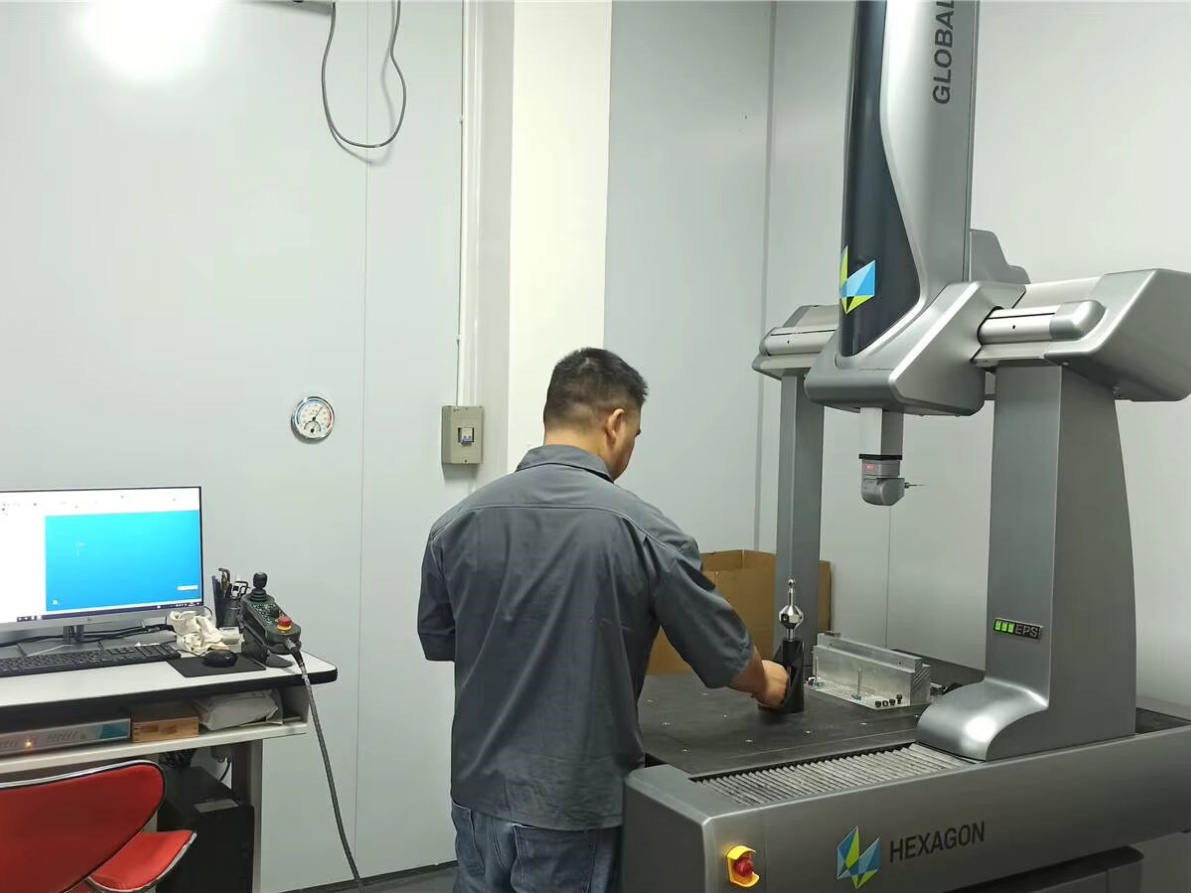
- Final inspection: Runout, roundness, and bore diameter logged against the drawing. Report ships with the part.
Process Route Reference: YPMFG process library, reviewed against published tooling data. Client-specific data withheld per NDA.
You can send your wheel drawing or specification to YPMFG for an engineering review before committing to a citation. The review flags any geometry that will force an extra setup or a secondary process.
What Should You Check Before Ordering a Milled Wheel?
Can a 3-axis machine hold a 0.01 mm runout?
No. A 3-axis setup realistically holds 0.03 to 0.05 mm runout. Below that, you need a 5-axis machine or a dedicated lathe-finishing pass, which changes the cost structure entirely.
What is the smallest bore a CNC mill can finish in one op?
It depends on the tool diameter. A 3 mm back-boring bar handles bores down to 8 mm in a single setup. Below 8 mm, you are into broaching or small-bore lathe territory.
Does material choice affect lead time?
Yes. 6061-T6 bar stock is typically in-house or ships within 3 days. 316L round bar often requires a 5 to 7 day procurement window. Confirm stock availability before locking a delivery date.
How do I verify the part before it ships?
Request a first-article inspection report against ASME Y14.5 or your applicable GD&T scheme. The report logs measured values for every critical dimension, not just a pass/fail stamp.
How Do You Pick the Right Milled Wheel for Your Assembly?
The three numbers that matter most on any milled wheel are runout, material grade, and the measurement plane. Lock those before you request a quote, and the shop can price the job in one pass without back-and-forth.
If you send your specification or drawing to YPMFG, the engineering team will cross-check your classe de tolérance,suggest a material substitute if it shortens lead time, and flag any geometry that forces an extra setup. You get a documented review and a firm délai de livraison before you commit to production. The next step is to send the part drawing with operating speed, environment, and expected service life stated.