Korean
 English
 German
 Russian
 Japanese
 Spanish
 French
 Italian
 Portuguese

A CNC controller with motor turning drives the spindle or rotary axis through a servo or stepper motor, closing the loop with an encoder at a fixed update rate. The controller converts a commanded position into a torque signal the inverter executes. That closed-loop cycle is what sets your achievable turning tolerance and surface finish on the finished part.
Most RFQs list a turning diameter and a tolerance but say nothing about the controller class behind the machine. You need to know whether the job runs on a 3-axis CNC 제어기 with one rotary axis or a 5-axis setup where the motor turning axis must synchronize with tool orientation. YPMFG reviews that layer before releasing a quote so the part geometry, material grade, and finish specification all land on a machine whose controller can actually hold the numbers you wrote down.
- Encoder resolution: A 16-bit incremental encoder produces 65,536 pulses per revolution. That figure sets your minimum angular increment and your practical CNC 선반 가공 resolution floor.
- Material-dependent speed: H13 steel at 800 rpm demands a different controller update cadence than 6061 aluminum at 4,000 rpm. The load on the servo differs by an order of magnitude.
- 공차 하한: ISO 2768-f on a turned bore is achievable on a well-calibrated servo. Going below 0.005 mm requires verifying the controller interpolation rate in writing.
What Does the Controller Command at Each Turning Cycle?
Each turning cycle is a three-signal loop. The controller issues a position command, the motor drive converts it to a torque signal, and the encoder reads back actual position. The difference between commanded and actual is the error the controller corrects on the next update.
The Three-Signal Loop
The update rate matters more than raw spindle speed for tight tolerances. A controller updating at 1 kHz tracks a step change in feed without overshoot. One at 100 Hz will overshoot and leave a visible mark on the finished bore. When you specify a part, ask which interpolation rate the machine runs on the axis you care about.
- Position loop: controller command → motor drive → encoder feedback
- Velocity loop: commanded spindle speed vs. actual rpm at the tool interface
- Thermal compensation: offset applied based on motor winding temperature each cycle

Check your machine’s controller manual for the interpolation frequency on the turning axis. If the spec sheet lists spindle speed but does not name the update rate, request the data directly from the manufacturer.
How Do Material and Tolerance Change Controller Requirements?
The same controller holds a 6061 aluminum part at 0.01 mm and struggles with H13 steel at 0.005 mm because cutting forces differ sharply. Stiffer material loads the spindle faster, and the controller must respond before deflection exceeds the tolerance band.
Thermal Load and Compensation
Materials like 316L stainless have lower thermal conductivity, so the spindle and workpiece heat up more per pass. The controller’s thermal compensation routine, not the raw encoder, keeps the dimension stable across a 20-minute turning sequence. YPMFG cross-references material grade, critical diameter, and tolerance against the available controller classes before recommending a machine.
Figure 1. Controller class comparison for turning operations. Axis count, not material, drives the split.
The split comes down to geometry, not material. A straight turned shaft in 304 stainless runs cleanly on a 3-axis controller. The moment your part has an angled face that needs the tool to tilt while the workpiece rotates, you need the 5-axis kinematic solve. YPMFG maps your part drawing to the right controller class during DFM 검토 before any tooling is cut.
Which Controller Specifications Should You Verify Before Placing an Order?
Three numbers on the spec sheet drive your decision: encoder resolution, controller update rate, and maximum synchronized axis count. Resolution tells you the smallest angular step; update rate tells you how fast the loop closes; axis count tells you whether the part fits in one setup.
Datasheet vs. Brochure
For tolerances tied to ASME Y14.5 or ISO 286, the controller’s interpolation must match the datum scheme. A part defined on a cylindrical datum with a profile tolerance needs the controller to hold radial and axial position simultaneously. That is a different load than a simple diameter tolerance. Request the controller datasheet, not just the machine brochure. The datasheet states the encoder bit count, update frequency, and supported axis count. If a supplier cannot produce the datasheet, treat the tolerance claim as unverified.
Rule of thumb: a 14-bit encoder at 50 Hz will not hold 0.005 mm on a long bore. Verify the numbers before you sign the PO.
Where Do Buyers Most Often Get the Controller Selection Wrong?
The most common error is specifying a tolerance without naming the controller class that must hold it. A buyer writes 0.003 mm on a turned bore and receives a quote from a machine whose controller updates at 50 Hz. The part may pass on the first sample and drift on the fiftieth.
Stepper vs. Servo
A stepper holds position by open-loop pulse counting. The moment friction or load spikes, it loses steps silently. A servo drive closes the loop with an encoder and recovers at the next cycle. For any part where a lost step means a scrap, you need servo.
A lost step on a stepper is a silent scrap. On a servo, the encoder catches it at the next cycle.
The Thermal Limit
No controller eliminates thermal growth in the spindle. Below 18 °C or above 30 °C ambient, the spindle housing expands and the encoder reference shifts. No software compensation fully cancels that physics. Plan your shop temperature before you plan your tolerance stack. This is a hard physical limit, not a spec-sheet gap.
Turned Shaft Process Route
- Rough turning: spindle at low rpm, deep cuts in 6061 or 304. Controller runs at a conservative update rate to keep tool deflection under control.
- Finish turning: spindle speed rises, feed drops below 0.1 mm per rev. The controller switches to its highest interpolation mode to hold the final diameter.
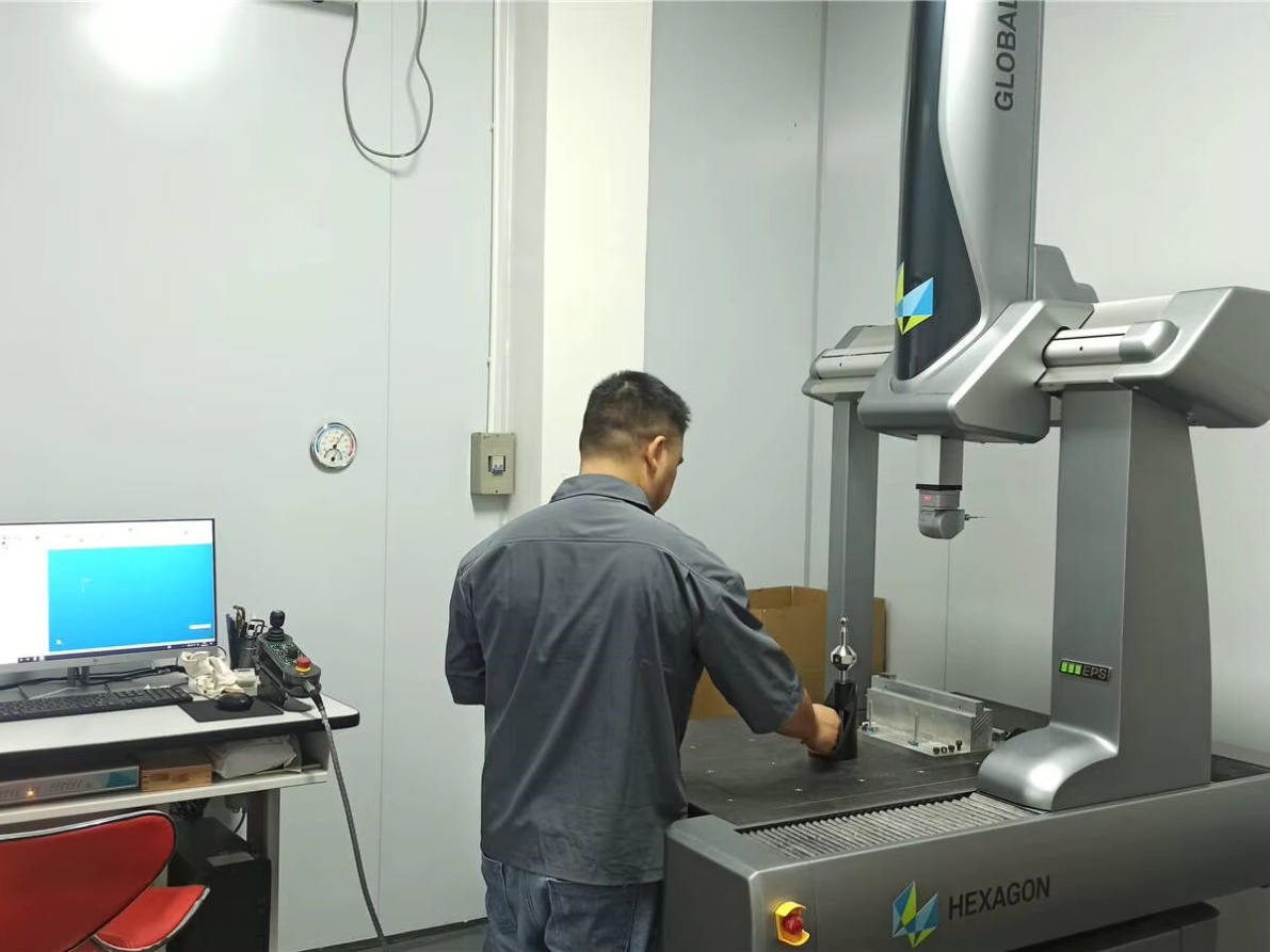
- In-process check: a CMM or bore gauge verifies the critical dimension at the 10th,25th, and 50th piece. Out-of-tolerance triggers a controller re-tram.
- FAI and batch: first-article inspection per ISO 9001:2015. Batch retention samples stay with the lot for full traceability.
Process Route Reference: YPMFG process library, reviewed against published tooling data. Client-specific data withheld per NDA.
Practical Questions Before You Specify a Turning Controller
Does a stepper controller handle 316L turning? No. Stepper drive loses steps under the higher cutting loads of 316L. You need a servo with encoder feedback to stay inside the tolerance band.
What is the practical resolution floor for a 16-bit encoder? That gives 65,536 steps per revolution, or roughly 0.0056 degrees per step. On a 100 mm diameter workpiece, that translates to about 0.001 mm of circumferential resolution.
Can one controller run 6061 and H13 back-to-back without reprogramming? Depending on the controller’s material library, it can swap speed and feed parameters automatically. If the library is empty, you must program two separate tool paths and verify both before the batch starts.
How do I verify a supplier’s tolerance claim? Request the FAI report and the controller datasheet together. Cross-check the encoder bit count and update rate against the stated tolerance before releasing the order.
Choosing the Right Controller Class for Your Turning Work
Getting the controller class right saves you from a category of scrap that no amount of post-process finishing can fix. YPMFG reviews every turned-part RFQ against the available CNC 제어기 architectures, flags any tolerance-to-encoder mismatches, and returns a written DFM note before tooling starts. Send your part drawing, material spec, and tolerance callouts to YPMFG and the engineering team will come back with a controller recommendation and a cycle-time estimate within one business day. You get a clear answer grounded in the machine’s actual specs, not a catalog PDF.