Korean
 English
 German
 Russian
 Japanese
 Spanish
 French
 Italian
 Portuguese

Dross is solidified slag that reattaches to the cut edge when melt cannot fully eject from the kerf. Controlling assist-gas pressure and pulse settings at the source cuts rework roughly in half. Post-processing such as grinding or tumbling is a fallback, not a fix.
Every laser-cut part that arrives with dross on the bottom edge costs you labor, inspection time, and sometimes a full rejection cycle. The problem tightens on thick 6061 알루미늄 또는 304 stainless plates where the kerf is narrow and molten material has no room to escape. YPMFG engineers see this pattern weekly when buyers forward sheets cut on low-duty-cycle machines. The fix almost always sits in three variables: gas pressure, travel speed, and nozzle-to-workpiece distance. None of them are free, and trading one against the other shifts cost somewhere else in the job.
Key Takeaways
- Assist-gas pressure: Dropping below 0.6 MPa on 6 mm 6061 lets melt pool back into the kerf wall and freeze as dross.
- Pulse frequency: Raising pulse repetition by 20 percent on 316L thins the melt layer and improves ejection without changing speed.
- Nozzle standoff: A 2 mm gap is the published sweet spot for fiber lasers on sheet under 12 mm; wider gaps widen the kerf and trap slag.
- Post-processing threshold: If dross exceeds 0.5 mm in height, tumbling will not clear it; you need CNC 가공 or wire EDM on the affected edge.
Dross Control vs. Post-Processing: Where the Cost Lands
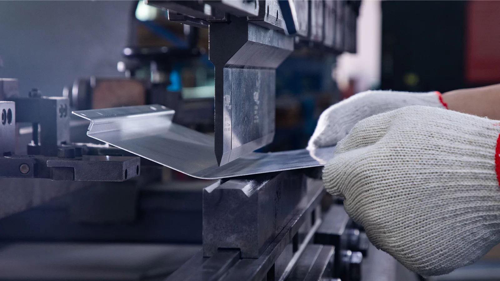
At-source control stays cheaper and more repeatable until dross height crosses half a millimeter, at which point post-processing becomes mandatory.
Why Dross Forms: It Is Not Just a Nozzle Problem
Dross is a momentum problem. The assist gas must carry every droplet of melt out of the kerf before the edges resolidify. If gas velocity at the cut plane drops below the melt ejection speed, slag wicks back down and freezes. Nozzle clogging and contaminated gas are the usual suspects, but they are symptoms, not the root cause.
Two factors do most of the damage: travel speed set too high for the plate thickness,and assist-gas pressure set too low for the material. On 304 stainless above 8 mm, a speed increase of even 10 percent can push the melt layer past what 0.8 MPa of nitrogen can clear. The operator sees a darker, rougher edge and assumes the nozzle is dirty. The real fix is a 5 percent speed pull-back, not a new nozzle.
What the laser cannot do: once dross has fused to the substrate metallurgically, no gas setting will release it. That edge is already a finished part; only mechanical or thermal reprocessing can detach it.
Which Assist Gases Actually Reduce Dross on 6061 and 304
The gas choice sets the ejection ceiling. 질소 at 0.8–1.2 MPa is the default for 6061 알루미늄 up to 12 mm because it oxidizes the melt surface and keeps it fluid longer. Oxygen works for mild steel but adds exothermic heat that actually thickens the melt layer, so it is the wrong call on alloy steels where you want a clean edge.
On 304 and 316L stainless, nitrogen is the only practical assist. The published tooling data from major laser OEMs confirms that oxygen on stainless raises dross height and introduces pitting in the heat-affected zone. Compressed air is a budget option; its moisture content makes it inconsistent for repeatable runs.
You can request a gas-and-parameter matrix for your specific alloy and thickness from YPMFG before committing to a supplier quote. The matrix lists pressure, speed, and focus offset as a starting set, which you then validate on a scrap coupon.
Thickness and Speed: Where Dross Becomes Unavoidable
Every material-thickness band has a speed window where dross is manageable and a speed above that window where it is not. The window narrows as thickness grows. On 2 mm 5052 aluminum you have a wide margin; on 16 mm 316L the margin is tight, and any speed overshoot drops slag onto the bottom face.
The physics is simple: deeper kerf means more melt volume and a longer path for gas to clear it. Fiber lasers with 10–20 kW output handle up to roughly 12 mm of stainless in a single pass with acceptable dross. Beyond that, you either stack passes (each pass re-melts and can re-dross) or switch to 5축 CNC 밀링 on the cut edge to clean up.

A limit to name: no gas pressure will fully clear dross on a single pass through 20 mm of 304. The kerf geometry is too narrow relative to the melt volume. The only honest answers are multi-pass with manual edge cleanup, or routing the part through a CNC mill for the final 0.5 mm face-finishing pass.
When to Stop Fighting Dross and Send the Part Downstream
There is a point where chasing zero dross at the laser costs more than a short downstream CNC 가공 pass. That point usually lands around a 0.5 mm dross height on functional edges, or any cosmetic face where the as-cut roughness exceeds your drawing spec.
Three signals tell you the laser has done its job and the next step is a different machine: the dross is fused (does not chip off with a brush), the edge is on a mating surface with a CNC 가공 공차 requirement, or the batch is small enough that a 15-minute mill setup beats an hour of tumbling. YPMFG can sequence that handoff if you send the part number and the critical-dimension callout.
What the laser will not do: hold a 0.05 mm flatness on a face that went through a dross-and-grind cycle. The heat input distorts the surface; only a subsequent milling or turning pass restores that level of flatness.
How Laser Cutting Handles a Stacked 6061 Bracket: A Process Route Walkthrough
A typical multi-layer 6061 bracket (4 layers, 3 mm each, stacked) asks the operator to cut 12 edges in one setup without disturbing the next layer. The dross risk concentrates on the top layer, where the melt pool is thinnest and gas ejection is fastest but also least supported by the substrate below.
The process route that keeps dross under 0.2 mm on all 12 edges goes in four steps. Step 1: cut the bottom layer first at a slightly slower speed to establish a clean reference edge. Step 2: flip the stack and cut the next layer at the same speed, using the already-cut edge as the in/out point to avoid a new pierce. Step 3: raise assist-gas pressure by 0.1 MPa for the top two layers, where ejection distance is longest. Step 4: run a 0.3 mm face-finishing pass on a 3-axis CNC to remove the last trace of slag on any mating face.
At each step the operator checks a witness coupon against the ASME Y14.5 GD&T callout. If the dross height on the coupon exceeds 0.3 mm, the speed drops 5 percent before the next layer. The control point is not the laser itself but the coupon check between layers.
Process Route Reference: YPMFG process library, reviewed against published tooling data. Client-specific data withheld per NDA.
Common Questions About Dross on Laser-Cut Parts
Does dross only appear on the bottom edge?
No. Dross can form on the top edge when gas pressure is too high and blows molten material upward. The pattern shifts with pressure, speed, and focus offset; you must check both faces on a witness coupon.
Can I just raise the gas pressure to fix it?
It cannot be that simple. Raising pressure widens the kerf and can blow dross onto adjacent features. Pressure, speed, and focus must move together; changing one in isolation usually makes another worse.
Is dross the same as burr on a sawn edge?
Dross is molten, re-solidified metal bonded by heat; a saw burr is a mechanical shear lip. Dross does not respond to deburring tools the way a burr does. You need the same removal path: grinding, tumbling, or a machining pass.
How do I know if my supplier controls dross or just ships it?
Ask for the last three witness-coupon photos at the thickest material in the order, plus the gas pressure and speed logged per layer. A supplier that tracks those numbers per batch is running a controlled process; one that cannot produce them is running a visual-only check.
Choosing the Right Downstream Step for Your Part
The decision between fixing dross at the laser and routing it to a CNC 가공 cell comes down to three things: dross height on the witness coupon, the tightest tolerance on the drawing, and batch size. Small batches with tight CNC 가공 공차 callouts usually lose money fighting dross on the laser floor; a 20-minute mill setup pays for itself on the first two parts.
YPMFG can review your drawing, the as-cut surface finish, and the critical-dimension callouts, then tell you in one call whether the part clears on the laser alone or needs a short milling or grinding step. You send the specification file; the engineering team returns a one-page process note with the recommended parameters and the dross-height limit that triggers the next operation. No minimum order, no obligation. The note is yours to keep whether or not the job lands here.