French
 English
 German
 Russian
 Japanese
 Korean
 Spanish
 Italian
 Portuguese

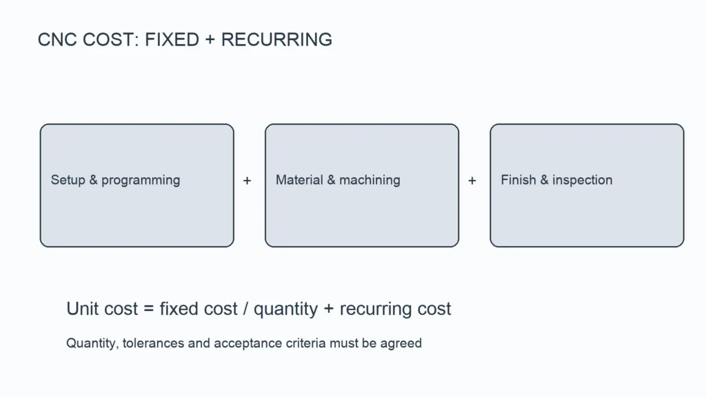
Machining dimensional variation is driven by three forces: spindle thermal drift, fixturing deflection, and progressive tool wear. Lock all three within your CMM gauge limits, and part-to-part spread on 6061 aluminum stays inside ±0.01 mm for features under 50 mm.
Most buyers discover dimensional scatter late, when a batch fails incoming inspection or the assembly line rejects parts week after week. The root causes are rarely mysterious once you open the machine logs. They trace back to thermal drift in the spindle housing, gradual fixture wear on datum faces, and tool geometry shifting across a long run. YPMFG reviews these variables during first article inspection so variation gets caught before scale-up, not after 2,000 parts are already cut.
Key Takeaways
- Thermal drift: A 1 °C spindle shift moves a 50 mm bore by 2–3 µm; run in a 20 °C ±1 °C environment to stay under 5 µm total.
- Fixturing strategy: Three-point hardened locator pins beat five-point soft-jaw clamps on thin walls; expect roughly 40% less radial runout.
- Tool overhang: End-mill overhang above 3× diameter pushes radial deflection past 5 µm; cap it at 2.5× for any bore tighter than ±0.02 mm.
What Actually Drives Dimensional Variation in a CNC Part?
Four physical factors set the floor on part-to-part spread: spindle thermal expansion, fixture compliance, tool geometry, and material anisotropy. You cannot eliminate all four, but you can rank them by contribution and bound each one.
Thermal Drift and Fixture Compliance
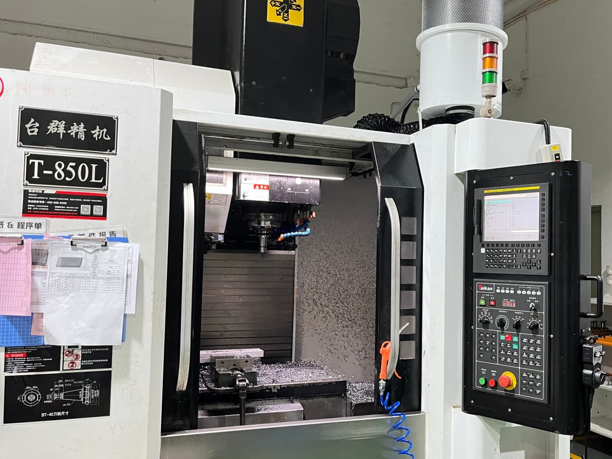
Thermal drift dominates longer cycles. A 45-minute run on a 3-axis CNC lets the spindle housing expand unevenly, shifting Z-axis repeat accuracy by several microns. Pre-heating the spindle for 15 minutes before batch start, or sequencing heat-critical features first, keeps this under 3 µm.
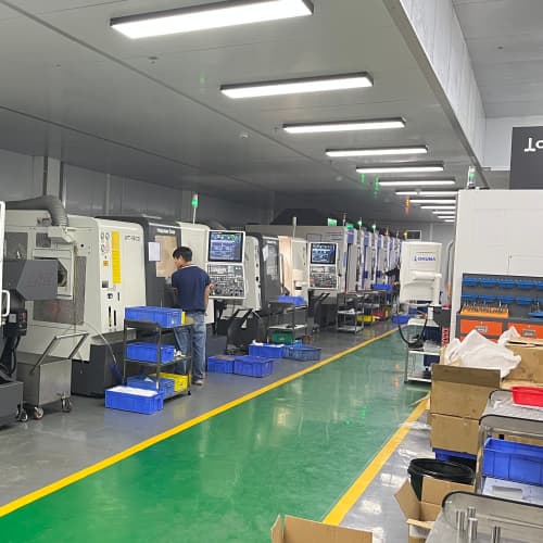
Fixture compliance hits thin-walled parts hardest. A 2 mm wall under 50 N clamping force bows 10–15 µm,then springs back on release. The dimension shifts every cycle unless the fixture design absorbs elastic recovery into a compliant interface.
GD&R and Process Capability
ASME Y14.5 GD&R callouts tell you where variation is functionally critical. A ⌀10 H7 bore on a bearing seat tolerates 18 µm; the same ⌀10 on a non-critical spacer tolerates 100 µm. Match your process capability to the datum scheme, not the tightest number on the print.
You can never drive thermal drift to zero without a temperature-controlled enclosure, and that cost lands on every part. The practical move is sequencing: cut thermal-sensitive features first at steady-state spindle temperature, leave low-criticality milling for the tail of the program.
Quel Tolérance Levels Keep Variation Tolerable in Production?
The answer depends on the standard you are held to. ISO 2768 mc covers general steel parts at ±0.1 mm. Classes c and f step down to ±0.05 and ±0.02 mm. Aerospace and medical work typically sits in the f class or below.
Reading the Tolerance Class
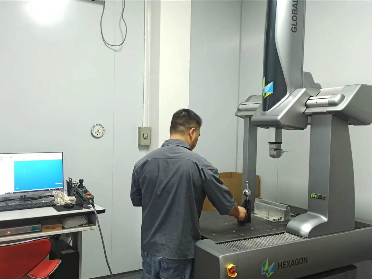
Below ISO 2768 f, you are paying for capacité du processus studies, tighter tooling, and more frequent CMM sampling. Confirm your supplier’s Cp is at least 1.33 before committing to a production batch.
If your assembly torque spec is under 5 N·m, the position tolerance is doing real work. Hold it at f class or tighter, and verify with a functional gauge, not just a CMM report.
How Do Material and Parameters Lock Your Tolerance?
Material picks the coefficient of thermal expansion, and CTE sets how much a part moves between machining at 22 °C and service at 80 °C. aluminium 6061 expands roughly 24 µm per meter per °C; 316L stainless expands about 17 µm per meter per °C. That gap becomes visible on features longer than 80 mm.
Material CTE and Service Temperature

Stiffer alloys like H13 tool steel resist fixturing deflection better, but they hold residual stress from heat treatment. Expect 2–5 µm of post-machining relaxation on a thick H13 block. Plan a 4-hour stress-relief rest between rough and finish passes.
Process Parameters That Actually Matter
Feed, speed, and depth-of-cut are the levers, but the real lock is on fixture repeatability and tool-change consistency. A 3-axis CNC holds ±5 µm on diameter when the work is clamped on a precision vise with hardened locator pins, not a soft-jaw setup.
Depth-of-cut changes chip load and heat input. Going from 2 mm to 0.5 mm radial leaves the surface cooler but doubles cycle time. For a 500-part batch where dimensional stability beats throughput, take the light pass. For a one-off prototype, go deep and accept the spread.
YPMFG reviews your print, fixture layout, and material heat-treat condition before quoting. Send the drawing and BOM; the engineering team flags which dimensions are thermal-sensitive and which need a post-heat-treat re-machining step.
One hard limit: below 0.01 mm total indicator reading on a round feature, standard 3-axis milling struggles. You will need a grind pass or a 5-axis setup with a shorter tool. That changes cost and lead time, and the honest answer is to tell your customer which features require secondary finishing.
How a Typical Bracket Goes From Print to Shipped Part
Consider a 120 × 80 × 15 mm 6061-T6 bracket: four ⌀8 through-holes, one ⌀12 H7 bearing bore, two 3 mm deep countersinks. Total spread target on the bore: ±0.02 mm.
- Rough mill: 3-axis, 2 mm radial, 4 mm axial. Cuts bulk. No dimensional check yet.
- Stress-relief rest: 4-hour rest lets micro-stresses settle. Skip it and expect 5 µm drift on the bore.
- Semi-finish: 0.5 mm radial, 0.5 mm axial. Bore within 0.05 mm of final dimension.
- Finish bore: 0.2 mm radial. Fresh end-mill, overhang ≤ 2× ⌀. CMM check every 25 parts.
- Countersinks and deburr: dedicated tool, no dimensional risk to critical features.
Process Route Reference: YPMFG process library, reviewed against published tooling data. Client-specific data withheld per NDA.
Common Questions Before You Specify Tolerances
Can a 3-axis CNC hold ±0.01 mm on a 60 mm feature? No. Standard 3-axis milling with a 10 mm end-mill typically holds ±0.02 to ±0.03 mm on that length. For ±0.01, you need a 5-axis setup with a shorter tool or a secondary grind pass.
Does material batch number matter for dimensional stability? Yes. Two 6061 ingots from different heats can differ in CTE by up to 2 µm per meter per °C. Specify alloy and temper, and request a mill heat-analysis report for every incoming batch.
How often should I CMM-inspect during a 10,000-part run? Start at every 50th part for the first 500. If Cpk stays above 1.67, stretch to every 200th. Any drop back to 1.33 means you re-tighten sampling immediately.
What is the cheapest fix for variation without changing the machine? It cannot be solved by adding coolant or slowing feed. The cheapest intervention is a better fixture: replace soft jaws with hardened locator pins and a repeatable datum. That alone cuts radial spread by roughly half.
Making a Better Decision on Your Tolerance Budget
Dimensional variation is not one problem; it is a stack of physical effects you can rank, bound, and cost. The buyer who specifies every feature at ±0.01 pays for capability most dimensions do not need. The buyer who leaves a critical bearing seat at ISO 2768 m walks with parts that never seat properly.
The practical move is marking which features are functional, which are cosmetic, and which are assembly-critical. Then match each to the tightest standard your process holds at acceptable yield. YPMFG can review your drawing against assembly requirements and flag which callouts drive cost, which can relax, and where a secondary operation saves a rework cycle.
Send your print, BOM, and target batch size. The engineering team returns a process capability estimate, a fixture recommendation, and a clear statement of which dimensions hold at the quoted tolerance and which need a grind pass. No obligation. Just a technical read of your part.