 Japanese
  English
  German
  Russian
  Korean
  Spanish
  French
  Italian
  Portuguese
 Quick answer:
G codes and M codes are the two core languages that drive every CNC lathe operation. G codes control the tool path and motion commands such as positioning, interpolation, and feed rate, while M codes handle machine functions like spindle start and stop, coolant control,and program end. Without a clear grasp of these codes, it is easy to misread machine output, select the wrong material, or push specs that a standard CNC lathe cannot reliably produce.
Most buyers do not need to write code from scratch, but they do need to read and evaluate it. Understanding CNC lathe G and M codes helps you verify whether a supplier understands your part geometry, confirms that their machine setup matches your tolerance expectations, and gives you a practical way to communicate deviations or revisions before mass production.
At YPMFG, we review customer drawings, suggest the most efficient CNC turning programs, and run engineering assessments to catch code mismatches early. The information below covers what these codes mean in real production, how they affect part quality and cost, and what to check when you share specifications with a machine shop.
What G Codes and M Codes Actually Control on a CNC Lathe
G codes and M codes belong to the ISO standard programming language used by nearly all CNC turning centers. They are not product names or proprietary features. They are functional instructions that the machine controller interprets step by step.
G codes define geometry and motion behavior. They tell the machine where to move, how to move between points, whether to use rapid traverse or controlled feed, and which interpolation mode to apply.
M codes define auxiliary machine actions. They usually switch on or off, manage workholding signals, trigger coolant, and handle program flow control such as stop and reset states.
Both code types work together inside a single part program. One line may contain multiple G codes, one or two M codes, axis positions, and feed or speed values.
Core G Codes Used in CNC Lathe Programming
G codes vary slightly between controller families, but the most common ISO G codes on CNC lathes follow a consistent logic. The codes below cover the functions you will see in the majority of production programs.
These codes form the structural backbone of any CNC lathe program. Understanding them helps you evaluate whether a supplier is applying the correct motion logic for your part features.
Core M Codes Used in CNC Lathe Programming
M codes are usually simpler than G codes, but they still carry important operational meaning. Each M code triggers a specific machine function that supports the cutting cycle.
M codes also control accessories such as tailstock advance, chuck clamping signals, and chip conveyor operation. Those custom or machine-specific M codes vary by manufacturer and are rarely part of standard buyer conversations.
How G and M Codes Affect Part Quality and Cost
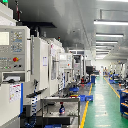
Code selection is not purely academic. The way a programmer writes G and M code directly influences cutting stability, surface finish, cycle time, and the likelihood of rework.
Using G96 constant surface speed instead of fixed RPM can improve surface finish on varying diameters. It keeps the cutting speed consistent as the tool moves toward or away from the spindle center.
Choosing G01 with proper feed per revolution instead of aggressive feed rates reduces tool wear and prevents deflection on slender or thin-walled components.
Overusing G00 rapid moves near finished surfaces can cause mark marks or interfere with chip flow. Programmers typically switch to controlled feed before final passes.
Improper use of G41 and G42 cutter compensation can generate radius errors or leave material behind on contour features. The compensation must match the actual tool geometry and offset table.
These choices may seem minor in a single program, but they multiply across batch production. Small programming inefficiencies often explain why two suppliers quoting the same drawing can show very different lead times and unit costs.
Why Code Standards Differ Between Controllers
CNC lathes from different manufacturers do not always behave identically. Fanuc, Mitsubishi, Siemens, and Haas controllers share a common ISO foundation, but each adds proprietary extensions and subtle logic differences.
A program written on one controller family may require adaptation before running on another. Common differences include canned cycle definitions, parameter settings for tool life management, and alternate memory handling for long part programs.
This is one reason why experienced CNC parts manufacturing shops evaluate your drawing first. They map your geometric requirements to the code strategy their machines handle most efficiently. That mapping reduces trial runs, avoids unexpected alarm states, and keeps the program stable across repeated production batches.
Common Mistakes Buyers Make When Evaluating CNC Lathe Programs
Many buyers focus only on final dimensions and surface finish while ignoring the program structure. That approach creates risk, especially when you are qualifying a new supplier or scaling volume.
One frequent mistake is assuming that a slower cycle time always means better quality. Sometimes a longer program includes unnecessary repositioning, redundant compensations, or overly conservative feeds that add cost without improving the part.
Another mistake is treating M code functions as optional. Signals like M08 coolant on, M06 tool change, and M30 program end are built into the machine logic for safety and repeatability. Removing or misplacing these codes can trigger alarms or incomplete machining cycles.
Some buyers also overlook the relationship between G90 absolute positioning そして G91 incremental positioning. Mixing both modes incorrectly can shift workpiece coordinate references and produce尺寸 drift between operations.
When you request a quote or engineering review, the supplier should confirm that the proposed code strategy matches your material, tolerance range, and delivery timeline.
What to Check Before Sending Drawings to a CNC Machining Shop
You do not need to write G and M codes yourself, but you do need to provide information that allows the programmer to choose the right code strategy for your part. Clear drawings, material specifications, and realistic tolerance targets reduce back-and-forth and keep the quotation accurate.
The checklist below covers the information that has the strongest impact on how a CNC lathe program is structured.
Confirm dimensional tolerances for critical diameters, lengths, and thread zones
Specify material grade and heat treatment status when relevant
Identify any feature that requires special tool access or unusual tool paths
Define surface finish requirements for functional and cosmetic areas
Clarify whether your design allows standard gripped or bar-fed stock lengths
Note any secondary operations such as threading, knurling, or cross-drilling
Indicate inspection points where CNC turning programs may need pauses or measurement cycles
If any of these items are unclear, a program will likely include extra safety blocks, longer tool paths, or additional compensations. Those adjustments increase cycle time and can raise cost.
How YPMFG Approaches CNC Lathe G and M Code Evaluation
We do not treat code selection as a black box. When a new project comes in, our engineers map your geometry to a suitable programming strategy first. They evaluate whether standard ISO codes are sufficient or whether machine-specific cycles offer a clearer path.
For complex profiles, we often prefer explicit linear and circular interpolation over hidden canned cycles. That approach gives us direct control over feed, depth of cut, and compensation logic. It also makes program review simpler when you ask for revisions later.
We run simulation checks before any first-article cut. This step catches collisions, verifies reference point returns, and confirms that G and M code sequences match the machine’s actual capabilities. If a feature falls outside reliable turning range, we flag it early and suggest a revised approach or a complementary process.
You can send your specifications to YPMFG for review. We will share a brief engineering assessment covering code logic, recommended material and process notes, and a quotation once the technical scope is clear.
How G and M Code Choices Impact Lead Time and Unit Price
Code efficiency is one of the quiet drivers behind lead time and unit price. A program that reaches the target dimension in fewer passes with stable chip control usually wins on both cost and schedule.
Longer tool paths, excessive compound cycles, and redundant stop blocks add seconds to every part. On small components those seconds add up quickly across large quantities.
Programs that rely heavily on manual intervention points, frequent coolant interruptions, or unstable compensation resets also increase variability. Variability slows sample approval and makes volume scheduling harder for both the machine shop and the buyer.
This is why we encourage customers to share roughness targets, tolerance zones, and batch sizes early. Those inputs shape the code strategy more than any single machining parameter.
Practical Questions Buyers Often Ask About CNC Lathe G and M Codes
Can a single CNC lathe program handle both metric and inch dimensions?
Yes, but the program must use either G21 for metric or G20 for inch consistently. Mixing both systems inside one program usually causes coordinate conflicts and dimension errors. The safer approach is to write separate programs for each unit system.
Why do some programs use G96 while others use G97?
G96 maintains constant surface speed, which is useful for consistent finish on changing diameters. G97 holds a fixed RPM, which is simpler and often preferred for short repetitive turns or hard materials. The choice depends on your surface requirement and material behavior.
Are G41 and G42 compensation safe to leave to the machine automatically?
Automatic compensation works well when the offset table matches the actual tool geometry and wear state. If the offset is incorrect, the program may cut undersized or oversized profiles without warning. Always verify the tool offset values before running first articles.
What happens if M00 or M01 is placed inside a cutting cycle?
An M00 pause stops all motion immediately until the operator presses cycle start again. An M01 optional stop behaves the same way but only activates when the optional stop switch is turned on. Both are useful for in-process inspection, but they extend cycle time if used unnecessarily.
Do different CNC lathe brands use completely different M codes?
Most M codes follow the same ISO base, but some brands assign extra functions to unused M numbers. Critical functions like M03, M05, M06, M08, M09, and M30 are widely shared. Custom or accessory M codes should always be confirmed with the machine shop before program exchange.
Should I ask the supplier to share the full program code?
You can request the program, but many shops share only a sanitized version for security reasons. The more useful document is usually the process sheet, tool map, and setup notes. Those documents reveal the code strategy without exposing proprietary nesting or proprietary routines.
How do I know if a quoted cycle time is realistic for my part?
Compare the stated cycle time with your expected feature count, material removal volume, and tolerance bands. Extremely low cycle times on complex parts often signal aggressive feeds, skipped compensations, or simplified programs that may not hold your tolerances in full production.
Choosing the Right CNC Turning Partner Based on Code Readiness
A supplier that understands G and M code logic will usually spot programming risks before they reach the machine. They can adjust your tolerance callouts, suggest feasible stock sizes, and recommend process sequences that align with standard lathe capabilities.
When you compare quotes, look beyond unit price. A cheaper quote built on unclear or over-simplified code logic often leads to rework, longer sampling cycles, and unpredictable batch performance. A clearer program strategy tends to produce more stable first-article results and smoother volume ramps.
You can request an engineering evaluation from YPMFG before committing to a quotation. Share your drawing, material, tolerance targets, and expected batch size. We will review the CNC lathe G and M codes implications, suggest a workable process approach, and return a transparent estimate with clear technical notes.