Italian
 English
 German
 Russian
 Japanese
 Korean
 Spanish
 French
 Portuguese

Send both when you can. A STEP file defines geometry; a 2D drawing defines intent, tolerances, and datums. Most shops that receive only one format will assume the missing detail, and that is where parts go wrong.
Your part went through three revisions before the first batch arrived. Each cycle cost a 3-day turnaround and a new setup fee. The root cause was never the CNC machine. It was an ambiguous 2D drawing that left a 0.2 mm feature up to interpretation, or a STEP file with no surface finish call-out so the shop defaulted to a 12.5 µm Ra. YPMFG engineers review incoming files before quoting to prevent exactly this. The question is not which format is better. It is which format carries the information your part actually needs.
Key Takeaways
- Geometry vs. intent: A STEP file locks 3D shape in 1 file but leaves 2D call-outs like tolerances and finish to a separate document.
- Datum and tolerance stack: ASME Y14.5 or ISO 2768 annotations live only on a 2D drawing; a standard STEP file carries no GD&T.
- Shop floor reality: 3-axis and 5-axis CNC operators need the model for CAM programming and the drawing for QC sign-off.
- Cost of ambiguity: One missing surface finish call-out can shift a part from a 3-day sample to a 15-day rework cycle.
The split is clean: geometry belongs in the STEP file, intent belongs on the drawing. If your part has a single critical fit or a finish that drives a downstream assembly, sending only the model leaves a gap no software can close.
What Does a STEP File Actually Carry into the Shop?
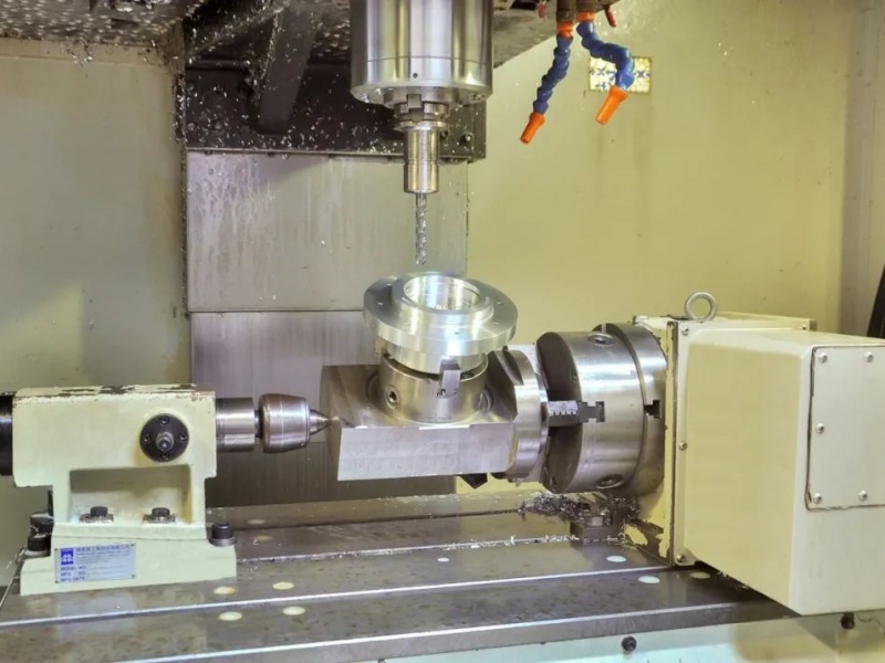
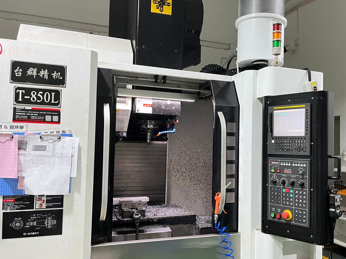
A STEP AP214 file stores the 3D B-representation: every face, edge, and vertex. It also carries material name, unit system,and sometimes a color layer. What it does not carry is a tolerance stack, a datum reference, or a finish requirement. For a 5-axis CNC job on 304 stainless, the programmer imports the model, generates tool paths, and machines to nominal geometry. That works until a clearance fit or a 3.2 µm Ra face appears.
The limitation is structural. The STEP standard was built for CAD data exchange, not manufacturing intent. You cannot write an ISO 2768-m default into a STEP file and expect every shop to read it. If a feature needs ±0.05 mm, that number must appear on a 2D drawing or in a note tied to a specific face. YPMFG engineers flag any critical dimension that lacks a call-out during the DFM review before the quote is released.
Physical limit: a STEP file can represent a solid at theoretical zero, but it cannot encode “this face must mate with a 316L gasket at 0.01 mm.” That relationship lives only in a drawing or an assembly instruction.
When a 2D Drawing Is Still the Right Call
Many parts in long-running series live entirely on a 2D drawing. The title block tracks revisions, the shop stamps the print, and QC compares the part to the view. For a 3-axis CNC milled housing in 6061 aluminum with a 15-day lead time, a clean 3-view drawing with ISO 2768-m tolerances and a 6.3 µm Ra call-out is all the shop needs.
The risk of drawing-only files is geometry ambiguity. A 45-degree chamfer shown at small scale can be read as 40 or 50 degrees. A STEP file removes that guess. If your part has a freeform surface, a thin wall under 2 mm, or a complex internal cavity, sending only the drawing forces the programmer to rebuild the 3D shape from views. That adds a 3-day modeling step and creates a single point of failure for geometry errors.
Physical limit: a 2D drawing cannot unambiguously define a complex 5-axis freeform surface. The operator has no reference to verify the shape without a 3D scan or a solid model.
Tolerances and Datums: Where the Two Formats Diverge Most
This is the section that saves you from rework. A STEP file gives you the nominal shape. A 2D drawing with ASME Y14.5 annotations tells you which face is datum A, which hole is position-toleranced at 0.1 mm, and which surface is 2.5 µm Ra. Without that layer, the shop machines to nominal and hopes the assembly fits. In a 316L valve body with a 0.02 mm clearance fit, hoping is not a strategy.
- Datum reference: Only a 2D drawing or a structured AP243 file carries a true datum scheme.
- Tolerance stacking: If 3 features feed one assembly envelope, the drawing must show the stack. A STEP file shows 3 features at nominal; it does not show accumulated error.
- First-article inspection: QC compares the part to drawing call-outs, not to the CAD model. The drawing is the legal reference.

YPMFG requests the GD&T layer or a tolerance table with every quote request. If the drawing is missing a datum, the DFM report flags it and the buyer confirms intent before the shop releases the part for machining.
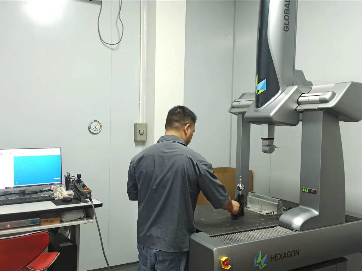
Physical limit: even with a perfect drawing, a 0.01 mm tolerance on a 304 stainless part is at the edge of what 3-axis CNC repeatability holds without thermal compensation. At that level, expect to discuss CMM verification before committing volume.
How YPMFG Handles Both and When You Need Both
For a typical 5-axis CNC job in 5052 aluminum, YPMFG asks for the STEP file for CAM programming and the 2D drawing for tolerance, finish, and QC reference. The STEP drives tool paths; the drawing drives acceptance criteria. Send only the STEP and the shop machines to nominal with a default ISO 2768-m finish. Send only the drawing and the programmer must model the part, adding 3 days to the schedule.
- Buyer sends STEP + drawing (or PDF with all call-outs).
- YPMFG DFM review checks for missing tolerances, ambiguous chamfers, and material call-outs (6061, 304, 316L, H13).
- Engineer returns a markup within 24 hours flagging any gap.
- CAM programming starts from the STEP; QC plan is built from the drawing.
- First article ships with an inspection report tied to the drawing revision.
Process reference: YPMFG DFM workflow, reviewed against ASME Y14.5 and ISO 2768. Client-specific tolerances and tooling data withheld per NDA.
If your part is a simple 2-axis milled spacer in ABS or Nylon, a 2D drawing with 3 views and a material call-out is sufficient. No STEP needed. The format you send should match the geometric complexity of the part, not a habit.
Practical Questions Before You Send Files
- Can I send only a STEP file and skip the drawing? No. A STEP file has no GD&T, no finish, and no revision history. For anything beyond a one-off prototype, the drawing is the acceptance document.
- What STEP standard should I export? AP214 is the minimum. If your CAD supports AP243 with 3D-annotated tolerances, use it. It cuts the number of separate files the shop must cross-reference.
- My drawing uses ISO 2768-m. Is that enough for a 304 stainless pump housing? It covers general tolerances up to 300 mm. Any feature tighter than 0.1 mm must be individually call-outed. Confirm each critical dimension separately.
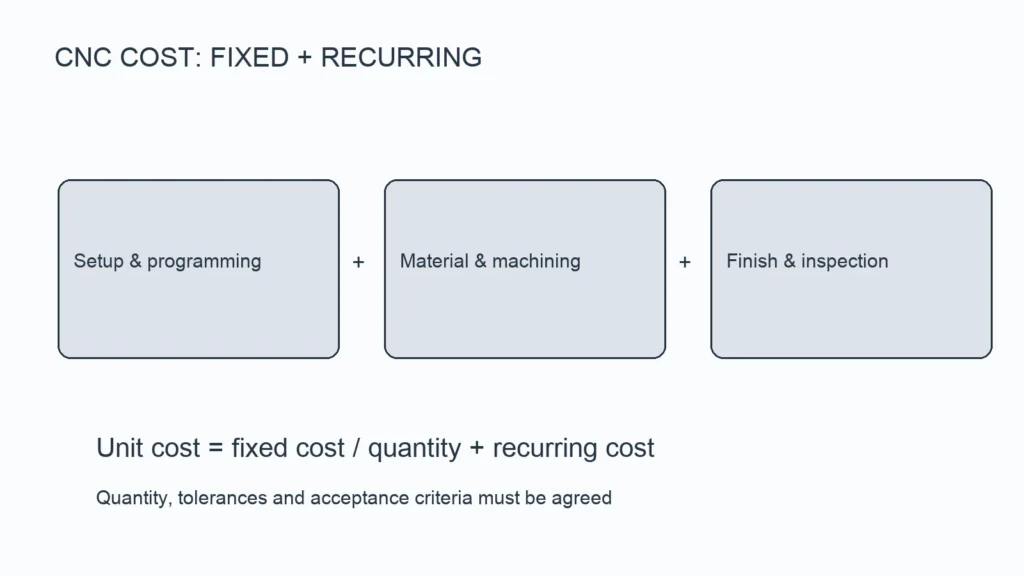
- Does the shop charge differently for STEP vs. drawing? CAM programming cost is the same either way. What changes is DFM review time. A clean drawing with all call-outs cuts the review from a full session to a quick pass.
Making the Right Format Decision Before You Hit Send
The cost of getting this wrong is not a rejected quote. It is a batch of parts that do not assemble, a 20-day rework window, and a revised BOM. The cost of getting it right is one additional file attachment. Before you email your specifications, check three things: every critical dimension has a tolerance value, every finished face has a Ra or Rz call-out, and your datum scheme is visible on at least one view. YPMFG engineers will review your file set and return a DFM note within 24 hours if you send both the STEP and the drawing. You get a markup that tells you exactly which face, which hole, or which chamfer is ambiguous before any material is cut. That one review step is cheaper than a scrap batch.