Japanese
 English
 German
 Russian
 Korean
 Spanish
 French
 Italian
 Portuguese

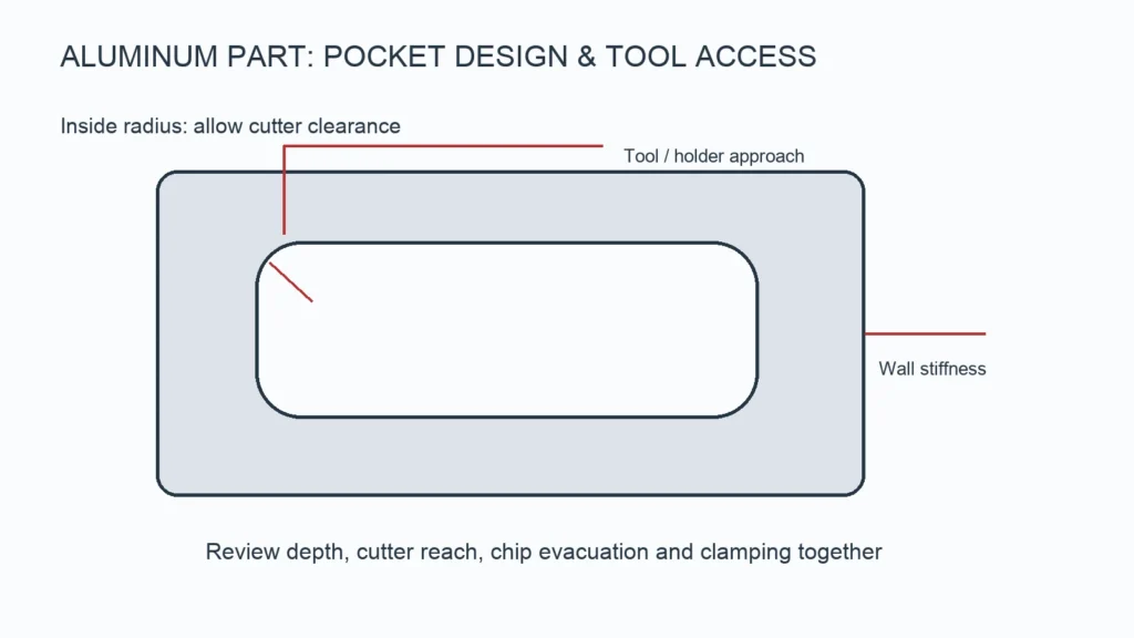
Aluminum parts machining becomes difficult when the cutter cannot reach a feature rigidly or the workpiece moves under cutting and clamping loads. A useful design review checks geometry, tool access and workholding together. There is no single minimum wall thickness or pocket depth suitable for every part.
Internal corners: design for a rotating cutter
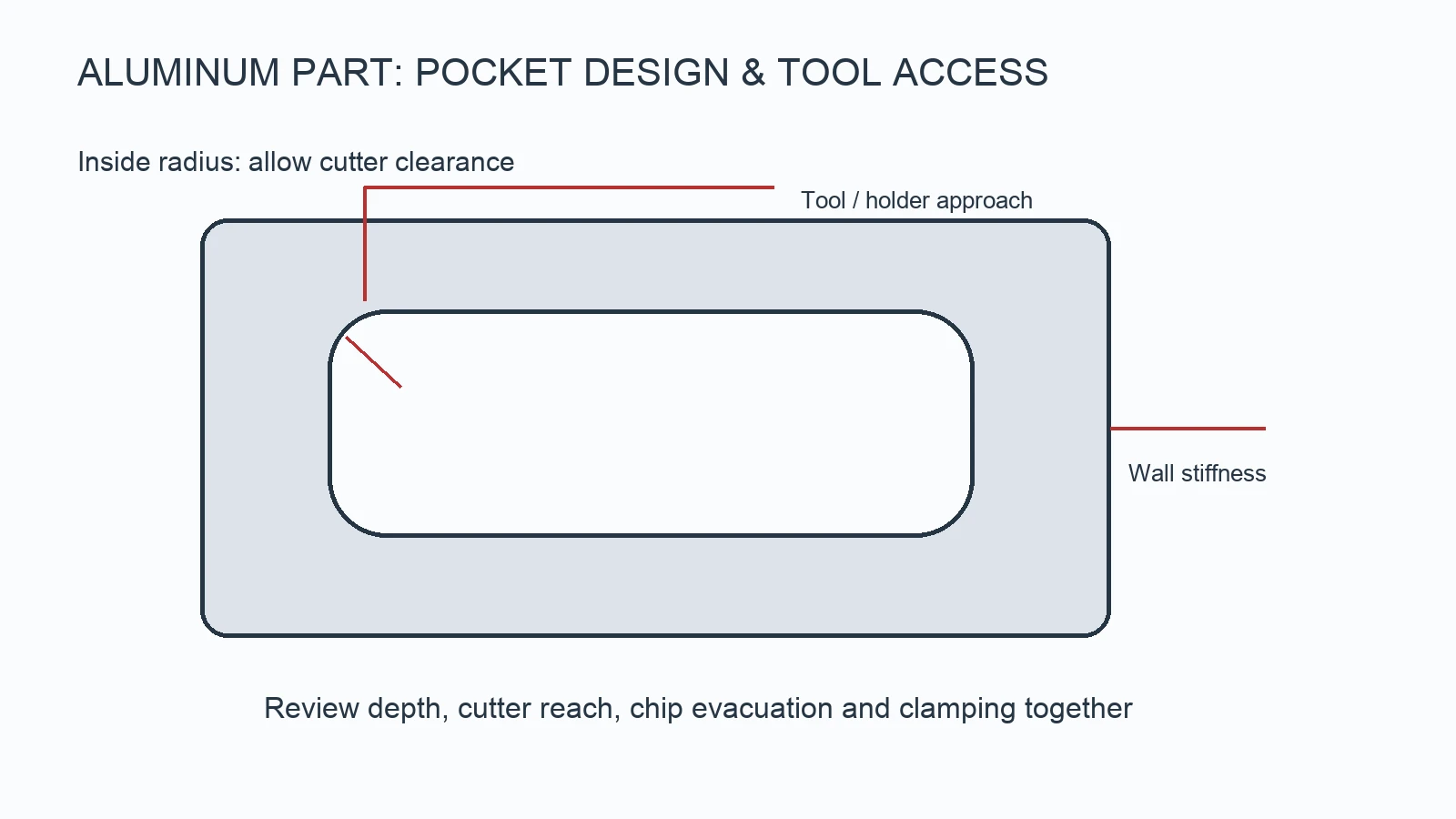
A cylindrical end mill leaves a radius in an internal vertical corner. If a mating square feature needs clearance, consider a larger corner radius, a relief feature or a revised mating geometry. A truly sharp internal corner may require a different process, such as EDM, subject to material and access.
Avoid making the specified internal radius exactly equal to the intended cutter radius without discussing the toolpath. Allowing a smaller cutter to interpolate the corner can improve cutting conditions. The best radius also depends on pocket depth and available tool sizes.
Deep pockets: separate cutting length from holder clearance
Pocket depth is only one constraint. The tool needs sufficient flute length for the cut, adequate shank clearance and a holder that does not collide with the wall. Longer tool overhang reduces stiffness and can increase deflection or chatter. Chip evacuation becomes more difficult in narrow, deep pockets.
For an illustrative design comparison, a 30 mm-deep pocket with a small corner radius may force a slender cutter, while the same depth with a larger radius may permit a stiffer cutter. This is a geometry comparison, not a guaranteed depth-to-diameter limit. Ask whether increasing the radius, opening one side or reducing depth would improve access.
Thin walls: stiffness depends on height and support
A short supported wall behaves differently from a tall unsupported wall of the same thickness. Consider wall height, unsupported span, local ribs, cutting direction and clamping position. Tool pressure and workholding can deform a feature that springs back after machining.
Review whether roughing can leave support stock, whether material should be removed more symmetrically and whether separate roughing and finishing operations are appropriate. Stress-relieved stock or an intermediate operation may help some designs, but does not guarantee zero distortion.
Datum strategy and setups
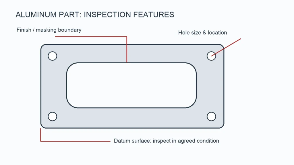
Features machined in one setup can avoid some relocation error, but a single setup is not always practical. Identify the mounting surface and critical hole relationships on the drawing. Ask how these features will be located during later operations and how the finished part will be inspected.
Five-axis access can reduce repositioning for some shapes. It does not automatically improve every tolerance or lower every price. Choose the process around access, rigidity and feature relationships. See our CNC milling service for project review.
Design problems and useful changes
| Problem | Review first | Possible design change |
|---|---|---|
| Chatter on a tall wall | Wall stiffness, tool overhang and engagement | Add support, reduce unsupported height or increase wall thickness |
| Corner cannot be reached | Tool radius and pocket depth | Increase radius or add approved corner relief |
| Part warps after release | Stock stress and material removal sequence | Improve symmetry, stock selection or process staging |
| Toolholder collision | Approach direction and surrounding geometry | Open access or change setup strategy |
| Critical fit changes after anodizing | Final-size requirement and masking | Define coating allowance or approved masked surface |
DFM FAQ
Is 1 mm or 2 mm a universal minimum wall?
No. Those numbers cannot define feasibility without material, height, span, tolerance and support conditions. Submit the actual geometry for review.
Can I machine a surface after anodizing?
Yes, but the operation removes coating locally. Specify exposed surfaces, corrosion protection and any subsequent treatment rather than treating post-finish machining as a routine correction.
What should accompany a CAD model?
Provide a drawing with material and temper, critical tolerances and datums, surface texture, threads, finish and revision. Use the aluminum inspection guide to define final acceptance.
図面のレビューを依頼する
YP-MFGでは、1個からのカスタム加工のご注文を承っております。3Dモデル、寸法入り図面、材質仕様、仕上げ、数量、および納品先を、当社の 見積依頼ページ. 通常、必要な情報がすべて揃ってから24時間以内にご返信いたします。技術的なご質問については、確定見積もりを出す前に詳細の確認が必要になる場合があります。