Japanese
 English
 German
 Russian
 Korean
 Spanish
 French
 Italian
 Portuguese

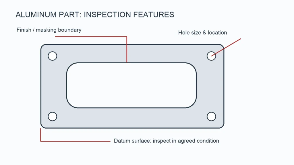
Aluminum CNC parts should be accepted against the drawing revision and agreed inspection plan. Appearance alone cannot confirm alloy, bore fit, hole position or flatness. This guide explains what to inspect, when to inspect it and which records make the result traceable.
1. Confirm alloy, temper and stock traceability
Specify the complete material designation, such as 6061-T6, together with the applicable product specification where required. Alloy, temper and product form affect properties; an alloy name alone is incomplete. Match material certificates to the supplied stock and link the material lot to the finished batch when traceability is required. A dimensional report does not establish material identity.
Do not accept 7075 as an automatic upgrade to 6061. Strength, corrosion behavior, finish appearance and service conditions must be reviewed by the designer. For material selection, see our アルミニウムのフライス加工ガイド.
2. Establish datums before measuring features
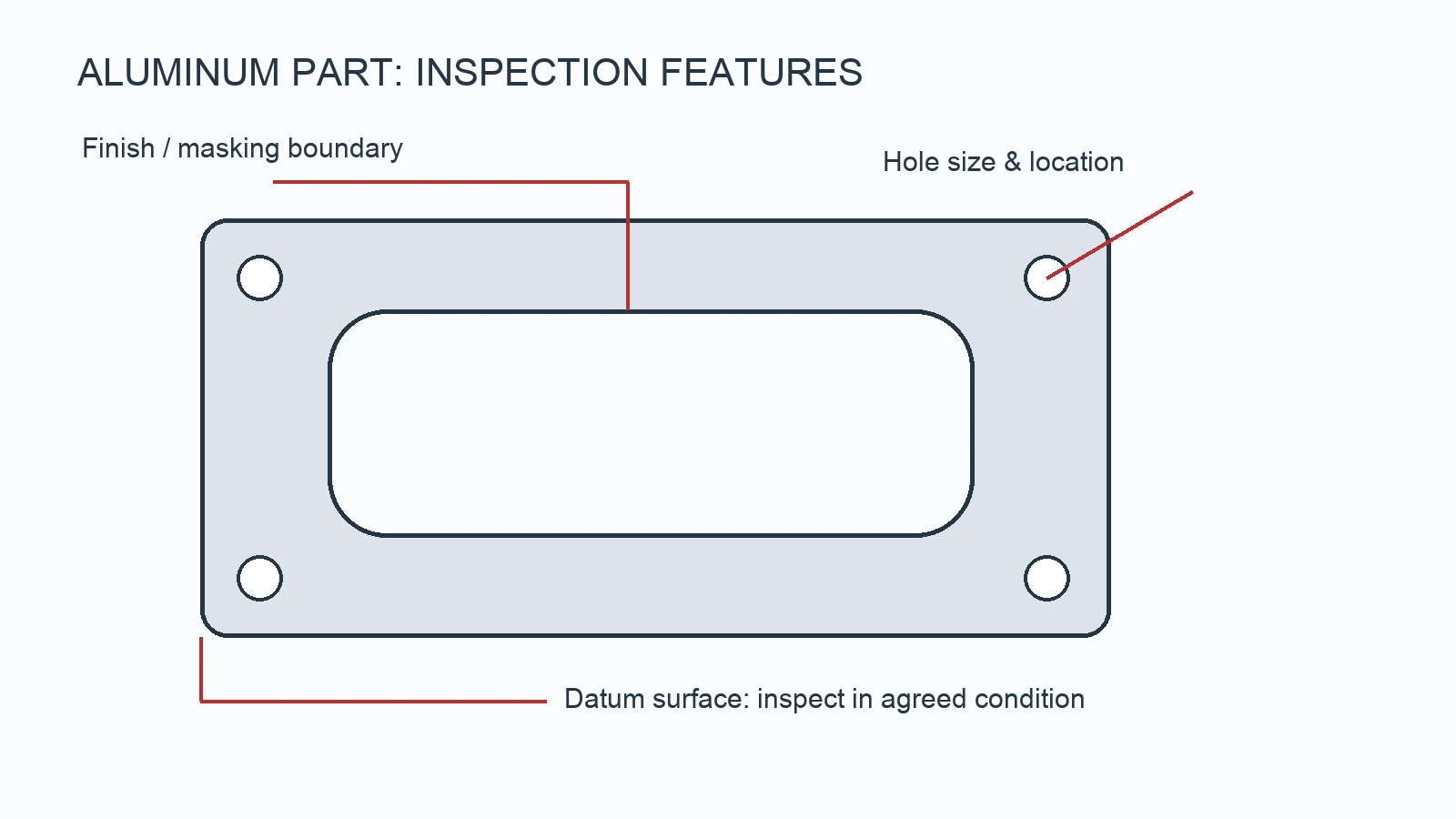
A datum reference frame defines how a part is oriented for measurement. A hole can have the correct diameter and still be in the wrong location. Inspect size and location separately, using the drawing’s datum order and geometric requirements. Do not substitute an edge-to-hole caliper reading for a specified positional tolerance.
| 特集 | Possible inspection approach | What to agree |
|---|---|---|
| 穴径 | Bore gauge, suitable plug gauge or CMM | Size limits, accessibility and measurement condition |
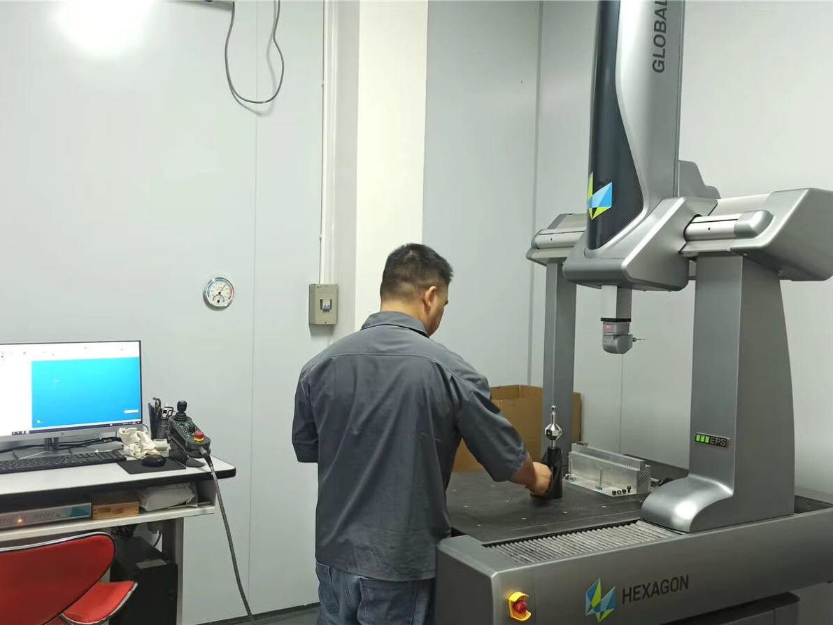
| Hole pattern | CMM or suitable fixture referenced to drawing datums | Datum simulation and positional requirement |
| Mounting face | Surface plate method or CMM as appropriate | Flatness requirement and support condition |
| Surface texture | Profilometer where required | Parameter, direction and applicable standard |
The instrument must suit the tolerance and feature. Measurement uncertainty, calibration, temperature and fixturing matter more as tolerances become tighter. A CMM is not automatically the best method for every dimension.
3. Inspect in the required finish condition
Anodizing converts aluminum at the surface and changes the effective dimensions of bores and external features. Total coating thickness is not the same as outward dimensional growth. Agree coating type, thickness range, masking and whether each critical dimension applies before or after finishing.
For a fitted bore, the drawing should state the final acceptance limits and whether masking is permitted. Do not apply a universal coating allowance to every alloy, geometry and anodizing process. Machining after anodizing is possible, but removes the coating in the machined area and must be planned.
4. Turn inspection results into an acceptance record
Use a ballooned drawing or equivalent characteristic list. Record drawing revision, nominal value, limits, actual result, instrument or method and inspected quantity. Specify whether the requirement is first-article inspection, sampled inspection or inspection of every part; these are different scopes.
Material certificates, dimensional reports and first-article documentation can be discussed with YP-MFG through our quality control team. Agree the scope and price before ordering.
Common inspection discrepancies
| Finding | Possible cause | Next check |
|---|---|---|
| Flatness changes after unclamping | Clamping deformation or residual stress | Support and free-state measurement condition |
| Bore fits before coating but not afterward | Finish allowance or masking not defined | Final bore limits and coating process |
| Hole size passes but assembly fails | Location, orientation or mating-part issue | Datum-based position and assembly stack |
| Cosmetic mismatch across batches | Material, surface preparation or finish variation | Agreed appearance sample and finish specification |
Inspection FAQ
Should every dimension have the tightest tolerance?
No. Assign tolerances from functional requirements. Blanket tight tolerances increase manufacturing and verification effort without necessarily improving assembly.
Can YP-MFG hold ±0.003 mm?
This may be available on suitable features after engineering review of geometry, material, size and inspection method. It is not a general acceptance tolerance for an entire aluminum part.
図面のレビューを依頼する
YP-MFGでは、1個からのカスタム加工のご注文を承っております。3Dモデル、寸法入り図面、材質仕様、仕上げ、数量、および納品先を、当社の 見積依頼ページ. 通常、必要な情報がすべて揃ってから24時間以内にご返信いたします。技術的なご質問については、確定見積もりを出す前に詳細の確認が必要になる場合があります。